
Related Manuals for Armstrong Delta2 FLY Series


Summary of Contents for Armstrong Delta2 FLY Series
- Page 1 IOM-576 v1 2 Ways Control Valve Installation and Operation Manual IOM 576 v1 – 16/07/2020 [Tapez ici]...
- Page 2 Armstrong Index Preface Scope 1. Installation 2. Recommandations 3. Commissioning 4. General Maintenance 4.1 Preventive and scheduled valve maintenance 4.2 Notes and instructions 4.3 Components Maintenance 5. Repair 6. Spare Parts List 7. Limited Warranty and Remedy IOM 576 v1 – 16/07/2020...
- Page 3 Preface For detailed material specifications, options, approximate dimensions and weights, see Armstrong literature or consult your local Representative. These control valve are manufactured to the strict standards of our ISO 9001 certified quality management system. It was tested for compliance with all applicable regulations and guidelines and fully conforms with all contractually agreed specifications.
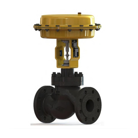
- Page 4 Scope These operating instructions shall apply to: - Two Way Control Valves (PN 6-250, Class 150-1500) - Three Way Control Valves (PN 10-160, Class 150-900) - Special valves "Taylor made" - Valves with fitted Pneumatic or Electrical linear actuator - Valves with or without accessories Product Description Control valves control gases, vapours or liquids and change the flow conditions of a process.
-
Page 5: Installation
1. Installation 1.1 "As delivered" status Valves are generally delivered assembled together with the actuators fitted and calibrated. All valves will be delivered after a complete test session required. Parts on the body and actuator subject to corrosion are protected by a coat of paint. 1.2 Transport Careful loading and transport arrangements are required to avoid the product suffering impacts and movements. - Page 6 Spare parts shall be requested by supplying the correct Serial Number (reported on valve plate located on yoke) to Armstrong office for a precise quotation. Armstrong valves will be supplied complete of a flow direction arrow on valve body casting. Where process and piping design permit we suggest the installation of:...
- Page 7 Any deviation from the standard installation not agreed with Armstrong can result in significant control deviations and in worst case expensive rerouting of the piping will be necessary. Instrument air supply shall be clean and dry and the temperature of the same should be ambient as per relative normative indications.
- Page 8 3. Commissioning When the valve is installed in the piping: Air Supply Connection For actuators without positioners, control air is connected directly to the air supply port of the appropriate actuator housing: - For direct-acting actuators (fail-open in case of 2-way) to connect to the upper housing - For reverse-acting actuators (fail-close in case of 2-way) to connect to the lower actuator housing.
-
Page 9: General Maintenance
4.1 Preventive and scheduled valve maintenance A preventive scheduled check and maintenance on control valves is suggested to have perfect efficiency from Armstrong control valves. Any leak or extra friction can reduce process performance and cause eventual delays with not scheduled maintenances. - Page 10 4.2 Notes and instructions Due to the risk of injury, it is prohibited to work between the yoke/columns area while the valve is in operation. 4.2.1 General notes for maintenance Before to start with any maintenance on the control valves please double check the following points: - Valve are pressure vessels.
- Page 11 4.3 Intro Components Maintenance Customer to be sure to provide proper overhead clearance for the actuator to allow for disassembly of the valve components for body. Refer to Table 1 for the clearance needed for valve disassembly. Table 1: Overhead Clearance Requirement Valve Size [mm] Minimum Top Clearance [mm] From DN.15 to 100 and with Actuator up to 430...
- Page 12 4.3.1 Actuator Diaphragm Replacement To Replace the actuator Diaphragm please read with attention the instructions and the pictures below. It is not necessary to disassemble the valve from the line nor the actuator from valve assembly. 1. Unscrew all actuator's bolting (pos.1) keeping the longer screws as last to discharge springs gradually.
- Page 13 4.3.2 Actuator Removal / Mounting Actuator Removal (Picture Page 15) 1. Disconnect actuator and valve stem by removing stem clamp bolts (pos.1) or joint for pillar yoke. WARNING: On fail-closed actuators, the preadjusted spring force is effective. Therefore, apply enough air pressure to the actuator to stroke the stem to the mid- position...
- Page 14 Reversing Actuator Action 1. Remove actuator from valve body (see Actuator Removal Procedures steps 1-6). 2. Remove the short diaphragm case bolts and nuts (pos.5) around the diaphragm chamber keeping longer bolts. 3. Remove thread covers from the long spring compression bolts. Lubricate the threads of the spring compression bolts with a light oil or grease.
- Page 15 4.3.3 Replacing Actuator stem seal 1. Remove actuator from valve body (see Actuator Removal Procedures steps 1-6). 2. Disassemble the actuator (see Reversing Actuator Action steps 1-5). 3. Remove the actuator stem (pos.3) through the lower actuator housing (pos.4). 4. The stem seal (pos.8) is pressed into the lower bushing stem guide. Remove the stem seal by wedging the blade of a screwdriver in the hole of lower bushing stem guide in the lower actuator housing.
- Page 16 4.3.4 Replacing Plug & Seat Replacing Plug 1. On fail-closed actuators, the preadjusted spring force is effective. Therefore, apply enough air pressure to the actuator to stroke the stem to mid- stroke before disconnecting actuator and valve stem. 2. Remove the bonnet nuts (pos.1). 3.
- Page 17 Bonnet Bolting Torque Values up to PN100 / #600 Valve Size mm / inches Metric Bolt Torque [Nm] DN15 to 25 / 1/2" to 1" M 10 DN32 to 50 / 1.1/4" to 2" M 12 DN65 to 100 / 2.1/2" to 4" M 16 DN125 to 200 / 5"...
- Page 18 Replacing Seat 1. Remove the actuator, bonnet and plug from the valve body (See Replacing Plug Procedure points 1- 2. Replace the seat ring using a suitable seat-ring tool. Seat-ring tool can be purchased from Delta 2 if required. 3. Apply high-performance lubricant to the threads on the seat ring. When refitting the seat ring, additives are also advantageous if compatible with the process fluid.
- Page 19 4.3.5 Stem Seals Replacing Packing Replacing 1. Disconnect actuator and valve see Par. 4.3.2.1 Actuator Removal 2. Remove the bonnet nuts (pos.1). 3. Remove the gland packing flange (pos.2) or nuts in case of External Live Loaded Packing being careful to avoid scratching the bonnet bore or the plug stem.
- Page 20 Bellow Backup Packing Replacing 1. Disconnect actuator and valve see Par. 4.3.2.1 Actuator Removal 2. Remove the bonnet nuts (pos.1). 3. Untight the threaded locking ring (pos.2) and depending on Bellow Seal type remove the gland packing flange (pos.3) or nuts in case of External Live Loaded Packing being careful to avoid scratching the bonnet bore or plug stem.
- Page 21 4.3.6 Spring Range and Stroke Adjustment Cast Yoke (Picture A) 1. On fail-closed actuators, the preadjusted spring force is effective. Therefore, apply enough air pressure to the actuator to stroke the stem to mid- stroke (50%) before disconnecting actuator and valve stem.
- Page 22 5. Repair Problem 1 - Stem motion impeded Probable Cause: 1. Overtightened packing 2. Service temperature is beyond operating limits of trim design 3. Inadequate air supply pressure Corrective Action : 1. Adjust packing box gland flange or Live Loaded nuts to slightly over finger-tight 2.
- Page 23 Problem 3 - Inadequate flow Probable Cause: 1. Improper plug adjustment, limiting stroke 2. Malfunctioning positioner 3. Service conditions exceed trim design capacity 4. Insufficient air supply pressure Corrective Action : 1. Refer to Stroke Length Adjustment for correct plug adjustment 2.
-
Page 24: Spare Parts List
6. Spare Parts List Body Stem plug nut Seat Actuator stem Plug Shaft guide Bonnet Actuator seal O ring Body gasket Actuator seal rings Stem bush guide Diaphragm closing plate Graphite ring Diaphragm V-rings Diaphragm plate Anti-extrusion ring Spring Packing spring Spring guide Packing gland nut Actuator nuts... - Page 25 Body Seat Plug Plug stem Bonnet Body gasket Bushing locking ring Stem bush guide Bellow seal Bellow seal gasket Pure graphite rings Packing bush guide Locking nut ring Spring washer Bellow seal locking ring Packing gland nut Valve bolts Stroke index Actuator pillars Lower pillar plate Upper pillar plate...
-
Page 26: Limited Warranty And Remedy
Armstrong: (i) within 30 days of last day of the applicable warranty period, or (ii) within 30 days of the date of the manifestation of the condition or occurrence giving rise to the claim, whichever is earlier.
Need help?
Do you have a question about the Delta2 FLY Series and is the answer not in the manual?
Questions and answers