Table of Contents
Advertisement
Quick Links
Installation and Maintenance
Water Temperature Controls
Groups of Fixtures - Thermostatic
Armstrong International
221 Armstrong Blvd., Three Rivers, Michigan, 49093 - USA
armstronginternational.com/brain
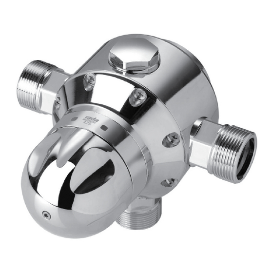
Model 425
Model No.
Serial No.
Ship Date
q Model 425
q Model 425D
:
:
Keep this manual with installation for
future reference.
Advertisement
Table of Contents

Related Manuals for Armstrong 425


Summary of Contents for Armstrong 425
- Page 1 Water Temperature Controls Groups of Fixtures - Thermostatic Model No. q Model 425 q Model 425D Serial No. Ship Date Armstrong International Keep this manual with installation for 221 Armstrong Blvd., Three Rivers, Michigan, 49093 - USA future reference. armstronginternational.com/brain...
-
Page 2: Table Of Contents
Contents Introduction .............. 3 Specifications ............5 General Advisory ............. 5 Safety ..............6 Pack Contents ............7 Schematic Piping ............. 8 Installation ............... 9 General ..............9 Installation Requirements ........9 Tools Required ............ 9 Installation Procedure ........10 Commissioning ............ -
Page 3: Introduction
166.6 174.1 185.5 Designs, materials, weights and performance ratings are Armstrong Hot Water Group, 221 Armstrong Blvd., Three Rivers, MI 49093 – USA approximate and subject to change without notice. Visit Phone: 269-279-3602, Fax: 269-279-3130 armstrong international.com for up-to-date information. - Page 4 166.6 174.1 185.5 Designs, materials, weights and performance ratings are Armstrong Hot Water Group, 221 Armstrong Blvd., Three Rivers, MI 49093 – USA approximate and subject to change without notice. Visit Phone: 269-279-3602, Fax: 269-279-3130 armstrong international.com for up-to-date information.
-
Page 5: Specifications
General Advisory This Model 425 Valve has been supplied for this application based upon information provided to Armstrong at the time the order was placed. This Model 425 Valve is configured for use in a “dead-leg” piping configuration. -
Page 6: Safety
The function of a Thermostatic Mixing Valve is to deliver water consistently at a pre-designated temperature. Model 425 Thermostatic Mixing Valves are precision engineered to give continued superior and safe performance provided: 1. -
Page 7: Pack Contents
Pack Contents X 1 q X 1 q X 1 q X 1 q X 3 q... -
Page 8: Schematic Piping
Schematic Piping Rada 425 Water Heater System Layout Thermometer Isolation Valve Sink Stop Valve Shower Flow Direction Check Valve Pipeline... -
Page 9: Installation
5. The Model 425 can be installed in both rising supplies and falling supplies. Installation Requirements The use of supply strainers will reduce debris entering the Model 425. The recommended gauge for such strainers is 35 mesh (mesh aperture dimension = 0.5mm). -
Page 10: Installation Procedure
Step 1 Step 2 Ø 6mm a. Use the Backplate to mark the two mounting holes at a. Unscrew the set screw. the desired height. b. Remove the Backplate. b. Drill the holes (6 mm) and fit the wall anchors. Screw the Backplate to the wall. - Page 11 Step 5 a. Hand-tighten all the nuts as shown above. Step 6 Step 7 a. Fully tighten all of the couplings using an adjustable a. Turn on the water supply and ensure that there are spanner. no leaks. Caution! Use a soft cloth to cover the plating from damage while tigtening with spanner.
-
Page 12: Commissioning
Commissioning Model 425 is designed for two types of configurations: 1. Locked Temperature (Temperature control is locked and cannot be adjusted) 2. Adjustable Temperature (Temperature can be adjusted through a desired range) The following steps show the procedure for both type of installations:... -
Page 13: Operation
Step 4 Exercising the Thermostat Thermostatic mixing valves with thermostats are inclined to lose their responsiveness if not used. Valves which have been in storage, installed but not commissioned, or simply not used for some time should be exercised before setting the maximum temperature or carrying out any tests. -
Page 14: Servicing & Maintenance
Model 425 can be completely serviced from the front/top and all of the internal components are replaceable. To access the valves internal components for inspection, cleaning or replacement proceed as follows. - Page 15 Step 3 Port Sleeve Assembly Thermostat Assembly Drive Nut Temperature Spindle Maintenance Procedure - Port Sleeve/Shuttle Assembly Retaining Cap Overload Spring Return Spring Shuttle Seat Shuttle Port Sleeve Screens Port Sleeve Assembly Push out shuttle from this end Disassembly Remove both port sleeve screens by releasing the folded tabs. To dismantle the shuttle and sleeve assembly, again insert the bar through the holes at the front of the port sleeve to hold the assembly whilst the retaining cap is loosened only using a spanner (50 mm) across the flats.
- Page 16 Cleaning/Renewal of Parts Internal parts (with the exception of the Thermostat Assembly) can be cleaned using a mild proprietary inhibited scale solvent e.g. domestic kettle descalent. After descaling, always rinse parts thoroughly in clean water before refitting. Note! The body interior must be cleaned carefully and not damaged in any way. Do not use any abrasive material.
-
Page 17: Spare Parts
Model 425 Spare Parts... - Page 18 Model 425 Spare Parts D77276 D77280 D77276 D58163 D79758 D58164 D77276 D58163 D58161 D58161 D77279 D58161 D33390 D77282 D33385 D77283...
- Page 19 Part No: Description D33385 Hub Pack D33390 Knob Pack D58161 Thermostat Pack D58163 Port Sleeve Pack D58164 Shuttle Assembly Pack D77276 1 - 1/4" NPT Connector Pack (two inlets, one outlet and one blanking plug) D77279 Drive Mechanism Pack D77280 Backplate D77281 Seal Pack - Not illustrated...
-
Page 20: Troubleshooting
Troubleshooting Fault Diagnosis Read the section “Important Safety Information” first. If any maintenance is required then it must be carried out by a competent tradesperson. Before replacing any parts make sure that the underlying cause of the malfunction has been resolved. Warning! There are no user serviceable components beneath the casing of the appliance. - Page 21 4. Hot water in cold supply a. Indicates non-functioning check valve Diagnose by turning off mixed water and vice-versa. (s). outlet flow and check to see if inlet hot pipe work becomes cold and vice- versa. 5. Mixed water a. Mixing Valve set too high and has not Refer to Commissioning - Rectify.
-
Page 22: Notes
Notes... -
Page 24: Limited Warranty And Remedy
Armstrong products, notice of any warranty or other claim relating to the products must be given in writing to Armstrong: (i) within 30 days of last day of the applicable warranty period, or (ii) within 30 days of the date of the manifestation of the condition or occurrence giving rise to the claim, whichever is earlier.
Need help?
Do you have a question about the 425 and is the answer not in the manual?
Questions and answers