Table of Contents
Advertisement
Quick Links
Steam & Water Hose Station and Mixing Valve
This Steamix Hose Station/Mixing Unit has been supplied for this application based upon information
provided to Armstrong at the time the order was placed.
In the event that this information was inaccurate or has since changed, product performance and user
safety may be compromised.
This Steamix Hose Station/Mixing Unit is supplied to generate hot water by mixing steam and water at
a single point of use within specific parameters for industrial applications only.
This Steamix Hose Station/Mixing Unit is not designed and should never be installed to deliver hot
water for hygiene or sanitary applications (people washing).
This Steamix Hose Station/Mixing Unit is not designed and should never be installed to deliver tepid
water to Emergency Fixtures.
This I & M covers the Steamix Model Numbers identified on page 3.
Specific model numbers can be determined calling our customer Hot Line at
1-888-HOT-HOSE and referencing the serial number.
Model No.
Serial No.
Ship Date:
U.S. Patent: 4,834,130
Steamix
Installation and Maintenance
™
ALIB-Steamix
Advertisement
Table of Contents

Related Manuals for Armstrong Steamix VE-M


Summary of Contents for Armstrong Steamix VE-M
- Page 1 ALIB-Steamix Steamix ™ Steam & Water Hose Station and Mixing Valve Installation and Maintenance This Steamix Hose Station/Mixing Unit has been supplied for this application based upon information provided to Armstrong at the time the order was placed. In the event that this information was inaccurate or has since changed, product performance and user safety may be compromised. This Steamix Hose Station/Mixing Unit is supplied to generate hot water by mixing steam and water at a single point of use within specific parameters for industrial applications only. This Steamix Hose Station/Mixing Unit is not designed and should never be installed to deliver hot water for hygiene or sanitary applications (people washing). This Steamix Hose Station/Mixing Unit is not designed and should never be installed to deliver tepid water to Emergency Fixtures. This I & M covers the Steamix Model Numbers identified on page 3. Specific model numbers can be determined calling our customer Hot Line at 1-888-HOT-HOSE and referencing the serial number. Model No. Serial No. Ship Date: U.S. Patent: 4,834,130...
- Page 2 7. Always check that the Maximum Temperature Lockout feature has not been tampered with or mis-adjusted before use. 8. Always wear water and heat protective gloves, garments, face protection, and safety glasses. 9. Only to be operated by persons trained in this equipmentís use and safety. 10. Always return the hose to its holder after use. 11. Always release the water pressure in the hose after use. 12. Always close (shut off) the inlet supply controls after use. 13. Only use this equipment for its intended industrial purpose: washdowns, vessel filling, and process applications. 14. Do Not substitute any component part on this assembly. 15. Use only performance matched parts for replacement from Armstrong Hot Water Group. 16. Use of incorrect parts could cause serious personal injury. 17. Do Not use attachments not authorized by the manufacturer. They may cause fire, electrical shock, or injury. 18. Do Not operate the equipment if it malfunctions, is dropped, or has been damaged in any manner. 19. Do Not operate this equipment if its hose is ripped or damaged in any manner. 20. Make certain that this equipment is properly installed before use. 21. Do Not, under any circumstances, use this product to supply hot water for human showering, bathing, or hand washing applications. 22. This product is unsuitable for use to supply water at any temperature for drench showers, eye wash stations or other emergency equipment. 23. If you have questions, consult this manual or call our Customer Hotline at (888) HOT-HOSE.
- Page 3 Introduction Steamix is a registered trademark of Armstrong Hot Water Group, a division of Armstrong International, Inc. ô Steamix is a brand of patented steam/water mixing valves and hose stations. For the purposes of this product manual, the model number STEAMIX 203 refers to the Mixing Unit featured on the Steamix Hose Station. Steamix 203 is ideal for vessel filling, hose down and similar process applications. Steamix is available in multiple derivative assembly configurations and subsequent model numbers. This Installation & Maintenance Guide covers the following Steamix Model Numbers along with the Nickel Plated Premium version which is identified with suffix ìSî. Contact us Toll Free at 1-888-HOT-HOSE to request a specific drawing. Model Number Drawing Number Standard Drawing Number Premium Steamix VE-M CDLW-1114 — Steamix VE-H CDLW-1121 — Steamix 2030H CDLW-1116 CDLW-1117 Steamix 2031 CDLW-1031 CDLW-1054 Steamix 2032 CDLW-1032 CDLW-1055 Steamix 2033 CDLW-1033 CDLW-1056 Note: CDLW Drawings will denote current production model as identified and may not be relevant for historical identification purposes This Installation and Maintenance Guide covers the following Steamix production generations. Classic 1990-1999 Serial Numbers A1000-A10000 Millennium 1999-2003 Serial Numbers A-L10000 — A-L13300 Infinity 2004 to present Serial Numbers A-L13300 and Above Product modifications and non-compatible replacement parts make Steamix generation identification mandatory prior to valve servicing or spare parts ordering. Refer to Page 14 or call our Customer Hot Line...
- Page 4 Operational Precautions / Safety Warnings 1. It is recommended that strainers always be installed (even if not supplied with unit) before Steamix 203 downstream of all other components including check valves. 2. Do not use this product with superheated steam. Failure to heed this warning may result in serious injury. 3. This product is designed strictly for Industrial Processes and Hose Down applications. Do not use for safety shower/eye wash stations, hand-washing or any other type of personal hygiene. 4. Do not leave the hose under pressure. Failure to follow this recommendation may lead to premature hose degradation and possible rupture. 5. The gland seal may have relaxed during shipment. Before use, firmly tighten the two gland screws equally using the 5/32î Allen key supplied. 6. Install steam rated inlet check valves on both steam and water supplies to prevent backflow through the mixing valve. Check valves will assist in the prevention of a cross connection in the event that Steamix flow controls are left open and an outlet flow control (spray nozzle) is closed. In addition, under certain circumstances, backflow may create a pressure differential across the diaphragm great enough to allow the poppet valve to open and steam to flow. Without inlet flow being present, this becomes a potentially dangerous condition. 7. Steamix 203 uses the supply steam so efficiently that it is possible to set the mixing valve to deliver boiling water that may flash to steam upon reaching the atmosphere at the valve outlet. This phenomenon should not be mistaken for valve failure or the passing of pressurized "live" supply steam. 8. Do not use petroleum-based lubricants on this product. 9. Use only Silicone-based lubricants. Warning: This product is designed to heat water for industrial washdown, vessel filling and process applications only. Access to extreme water temperatures and flash steam is a possibility. To avoid serious injury use extreme care and wear protective gloves, garments and safety glasses at all times.
-
Page 5: Theory Of Operation
Theory of Operation Steamix 203 produces hot water by mixing steam with cold water. The hot water temperature is variable from cold to almost boiling by rotating the temperature regulating lever counter-clockwise. If desired, the temperature can be locked at a pre-selected level by removing the temperature regulating lever and further secured by installing Part No. 042 tamper resistant locking Set. (See page 22.) Inlet water pressure activates the mixing valve allowing steam to heat the water. The valve requires a minimum inlet water pressure of 20 psig (1.4 bar) to open the steam inlet. This method of operation provides a built-in safety feature where the mixing valve automatically shuts off the steam supply when a water supply failure or a pressure reduction below 20 psi (1.4 bar) occurs. The following diagrams illustrate the mixing valveís method of operation. Figure 5-1. With the outlet closed and no flow, the water Figure 5-2. Opening the outlet allows water to begin to flow. When a pressures on either side of the diaphragm are equal. This minimum differential pressure of 7 psi (.5 bar) develops across the allows the spring to hold the poppet valve on its seat diaphragm*, the diaphragm lifts from its resting position and pushes the thereby preventing steam flow. poppet valve off the steam seat allowing steam to flow. By allowing steam to flow only when inlet water flow is present, the operator is protected from accidental exposure to live steam should the water supply fail. The poppet valve is resisted by the temperature control lever which allows more or less steam into the mix for higher or lower outlet temperatures as adjusted. *a minimum of 20 psi (14.4 bar) water pressure is required to lift the diaphragm. Figure 5-3. Closing the outlet valve increases back pressure. When the differential pressure across the diaphragm becomes less than 7 psi (.5 bar) or the water pressure is reduced below 20 psi (1.4 bar) the spring pushes the poppet valve closed, shutting off the steam flow and the diaphragm returns to its resting position. -
Page 6: Temperature /Pressure
Temperature /Pressure ! Minimum Steam / Water pressure: 20 psig (1.4 bar) ! Maximum Steam / Water pressure: 150 psig (10 bar) The STEAMIX 203 produces hot water at its outlet by mixing steam with cold water. This process uses the direct relationship: the greater the steam pressure, the greater the temperature rise ( r T) of the outlet water the greater the steam pressure, the greater the flow rate obtained on reaching the desired operating temperature. In situations where only very low steam pressure is available the mixing valve will still function properly but a large reduction in the outlet flow rate will occur. Optimum performance occurs when steam is in the 50 - 75 psig (3.3-5 bar) range and the water pressure is 50-75 psig (3.3-5 bar). Steam supply lines must be adequately sized to deliver a sufficient volume of steam. Water supply lines must be adequately sized to deliver a sufficient volume of water. Do not use this product with superheated steam. Failure to heed this warning may result in serious injury. Steam Consumption To approximate the amount of steam consumed during operation proceed as follows: 1. Measure, calculate or approximate the outlet hot water flow from Steamix. Review the flow charts on Page 7 but be sure to acknowledge the presence of any outlet fitting such as a Spray Nozzle* at the end of a Washdown Hose in a Hose Station application. *For approximation purposes use 7 GPM to rate the Spray Nozzle. 2. Note the inlet cold water temperature (T1) and desired outlet hot water temperature (T2) and establish the Temperature Rise based upon the differential (T2-T1). 3. Apply the following formula. Lbs per Hour = GPM/2 X (T2-T1) Warning: This product is designed to heat water for industrial washdown, vessel filling and process applications only. Access to extreme water temperatures and flash steam is a possibility. To avoid serious injury use extreme care and wear protective gloves, garments and safety glasses at all times. - Page 7 Flow Rates / Temperature The following capacity charts indicate Steamix 203 flow rates at steam and water pressures commonly available in the average manufacturing plant. The mixing valve can handle a wide diversity of pressures and temperatures. The three typical outlet temperatures shown in the tables demonstrate the mixing valves flow rate at: 1. "User Safe" temperature (approximately 120 °F/48 °C). 2. "Hot Hose Down" temperature (approximately 150-160°F/65°-71°C). 3. "Common Bacteria Kill" temperature (approximately 180°F/82°C) . The phrase "Common Bacteria Kill" is not meant to imply sterilization capability. However, Steamix 203's design allows it to handle the higher temperatures required in Food, Beverage, and Pharmaceutical Facilities. 55∞ F (31∞ C) Temperature Rise Steam 20 (1.4) 45 (3) 75 (5) 100 (7) psi (bar) Water 22 psi (1.5 bar) 9.6 ( 26.1) 10.2 (38.6) 10.2 (38.6) 10.2 (38.6) gal/min (l/min) 45 psi (3 bar) 9.6 ( 26.1) 13.2 (49.9) 13.2 (49.9) 13.2 (49.9) gal/min (l/min) 60 psi (4 bar) 9.6 ( 26.1) 13.8 (52.2) 15.7 (59.4) 15.7 (59.4)
-
Page 8: Installation
Installation Installation of Steamix 203 Mixing Valves and Hose Stations must comply with the relevant Federal, State and Local Sanitary, Construction, and Plumbing Code requirements. 1. When installing the mixing valve and associated fittings, position the valve to permit easy access for adjustment and servicing procedures. 2. Steamix Hose Stations and Mixing Units are supplied pre-assembled and pressure tested. All components are precision fitted by professional fully trained assemblers using an anaerobic thread sealant. Failure to "Hold Back" when piping to the unit will cause component shift which will compromise the assembly and may lead to leakage. 3. Install shut off valves on each inlet. Install shut off valves in a location which discourages tampering by the operator. Temperature and Flow must be controlled strictly at the Mixing Unit/Hose Station. 4. Install check valves on both inlets to prevent backflow through the mixing valve. Check valves will assist in the prevention of a cross connection in the event that Steamix flow controls are left open and an outlet flow control (spray nozzle) is closed. In addition, under certain circumstances, backflow may create a pressure differential across the diaphragm great enough to allow the poppet valve to open and steam to flow. Without inlet flow being present, this becomes a potentially dangerous condition. 5. Install unions on each inlet supply (factory supplied on specific models). 6. If the unit is to be hard piped from its outlet, then install a union at the outlet to facilitate servicing. 7. If not supplied by the Armstrong Hot Water Group, install a thermometer in the outlet pipe work for ease of temperature monitoring and adjustment. 8. Secure the mixing valve or hose station to a wall or column using the pre-drilled mounting plate provided for this purpose. The weight of the unit should not bear directly on the pipework. 9. Hose Stations include a rugged stainless steel hose carrier and backplate pre-drilled to facilitate anchoring. Back Flow/Back Siphonage Prevention In addition to check valves, the installation must comply with Local and State Codes, as well as the requirements of any Agency responsible for the inspection of, or compliance with Federal Regulations relating to your industry. This may include the installation of single or double action Back Flow Preventer and/or Vacuum Breakers. -
Page 9: Start-Up Procedures
Plumbing Recommendations 1. Always install strainers (even if not supplied with unit) immediately before Steamix 203 and down-stream of all other components including Check Valves. Install strainers with the arrows pointing towards the mixing valve when placed in horizontal or vertical supplies so that the strainer screen traps debris. 2. If widely fluctuating steam pressure is a common occurrence, a pressure regulator set to the lowest pressure encountered should be installed a minimum of six feet upstream from the mixing valve. 3. It is recommended a steam trap be installed on the steam supply piping upstream of Steamix 203 to evacuate or return the condensate. Trap should be installed at least 6 feet away but no greater than 15 feet away from the inlet of Steamix 203 where possible. 4. Inlet check valves. 5. Unions. Start-Up Procedures Prior to operating the valve, the outlet temperature must first be set within the required operating parameters as specified by plant management. The available temperature range of the mixing valve is from ambient inlet water temperature to almost boiling. To set the mixing valve to the required temperature: 1. Turn the temperature regulating lever clockwise as far as it will go to close the steam inlet. (This may take several revolutions.) 2. Remove the water flow regulator locking cap using a 3/32" Hex Key to loosen the set screw located at the base of the cap. Fully open the cold water regulator by turning it counter-clockwise. The mixing valve is now in the full cold position. 3. -
Page 10: Operating Procedures
Most wash down procedures benefit from the operatorís ability to vary the temperature as required. However, the temperature regulating lever can be removed and/or a tamper resistant "Lock Set" (optionally available part # 042) may be installed to prevent further temperature adjustment. Instruct all operators not to tamper with the water flow restrictor. For further details on #042 tamper resistant ìlock setî turn to page 22. Operating Procedures The Steamix 203 uses the supply steam so efficiently that it is possible to set the mixing valve to deliver boiling water that may flash to steam upon reaching the atmosphere at the valve outlet. This phenomenon should not be mistaken for valve failure or the passing of pressurized "live" supply steam. Daily Operation 1. Instruct all operators on basic safety procedures. 2. Do Not select a higher outlet temperature than required for process or wash down water. Using water that is too hot for the application is unsafe, wastes energy and may lead to inefficient clean-up. 3. Always shut off steam/water flow at the tandem valves. 4. Do Not leave the outlet hose under pressure. Bleed pressure by opening the outlet hose nozzle briefly. 5. Check the inlet supply shut-offs regularly. 6. Report any malfunction immediately to appropriate maintenance personnel. Safety Check 1. Set the mixing valve for normal operation. 2. Start outlet water flowing. 3. Shut-off a remote inlet water supply stop valve. 4. Outlet water flow should cease immediately without any ëliveí pressurized supply steam being passed from the mixing valve. 5. If live steam is passed during the test do not use valve or hose station. Initiate maintenance procedures immediately. Note: Testing of the intrinsic safety steam shut-off feature on a shift or daily basis does not degrade the unit. Warning: This product is designed to heat water for industrial washdown, vessel filling and process applications only. Access to extreme water temperatures and flash steam is a possibility. To avoid serious injury use extreme care and wear protective gloves, garments and safety glasses at all times. - Page 11 Diaphragm Performance and Durability Steamix 203 operates on a pressure actuated diaphragm principle as discussed on page 5 of this manual. A specially designed double-coated elastomer, high performance diaphragm has been custom designed for this application based upon extensive research and laboratory and field-testing. Diaphragm Service Life A chronological operational service life of a diaphragm is virtually impossible to specify due to the wide diversity of field application, inlet steam and water pressure and outlet flow temperature which Steamix experiences. Steamix diaphragms are continuously cycle tested at our state of the art test facility in Three Rivers, MI and the diaphragms must be able to exceed 50,000 field simulated operational cycles at the maximum steam pressure rating of 150 psi. In real terms that equates to approximately 50 wash down cycles every day for three years. Some diaphragms last longer (we have on record installations still fully operational at 12 years and counting), some do not last as long, which is why we offer a full replacement two-year warranty. Safety A diaphragm is a mechanical component in a mechanically operated product. All mechanical products have the potential to fail at some point in their service life. Steamix is the only product supplied for this application, which we are aware, that will fail to cold water flow in the event that its primary operating component (diaphragm) experiences failure. Tips for Ensuring Long Diaphragm Service Life 1. Cool Down: Do not use a spray nozzle as a long-term flow control device. Turn the Steamix off at its inlet flow control when it is not in use and let the valve cool. Itís good for the nozzle, itís good for the hose, itís good for the diaphragm. 2. Steam Quality: Maintain your steam system efficiently and watch the condensate chemistry. Highly acidic carbonic acid is not good anywhere in the system and the diaphragm is no different. 3. Trap: Trap the steam line feeding the Steamix effectively. Compounding large quantities of acidic condensate with water hammer and pressure shocks can cause all sorts of problems and again the diaphragm can suffer. By maintaining a reasonable distance (we suggest 6 feet) between the steam trap and Steamix, the cooled condensate in the pipework between the steam trap and Steamix will assist with Tip #1. 4. Back Pressure: Keep an eye on the pressure loss ratio discussed on page 12 of this Product Manual. High back pressures combined with diverse inlet pressures make the Steamix work extra hard and additional stress is placed upon the diaphragm. 5. Keep it Low: Steamix is rated for use with up to 150 psi steam. However, the outlet flow rate and temperature rise does not improve dramatically beyond 100 psi steam. In other words, we do not need steam pressures higher than 100 psi for effective, high temperature washdown. When possible, lower the inlet steam pressure to 100 psi or below. Tests have shown us that the extra 30 degrees or so which 150 psi steam gives you can really intensify temperature related fatigue on the diaphragm and seals within Steamix. Optimum performance pressures are noted on Page 6 of this manual.
- Page 12 Pressure and Pressure Loss Ratio Minimum and Maximum Pressures The minimum inlet pressures are: Water - 20 psig (1.4 bar) Steam - 20 psig (1.4 bar) Note: Low inlet pressures will significantly reduce outlet flow. The maximum static pressures are: Water - 150 psig (10 bar) Steam - 150 psig (10 bar) Pressure Loss Ratios: Maximum pressure loss across the mixing valve (inlet to outlet): 60 psi (4 bar) Minimum pressure loss across the mixing valve (inlet to outlet): 7 psi (.4 bar) Maximum pressure loss ratio is 10:1 in favor of either supply. Pressure Loss Ratio (PLR) is the ratio of steam and cold water supply pressures minus the back pressure caused by the outlet fittings and additional pipework, hose, or nozzle. Example: If the back pressure developed at the valve outlet was 45 psi (3 bar) and the steam pressure is 100 psi (6.6 bar) with a water pressure of 50 psi (3.3 bar) the calculation for PLR would be: 100 - 45 = 55 psi and 50 - 45 = 5 psi Thus, the pressure loss ratio is: 55: 5 or 11:1*. 6.6 bar - 3 bar = 3.6 bar and 3.3 bar - 3 bar = .3 bar Thus, the pressure loss ratio is: 55: 5 or 11:1*. *This unit will not operate effectively. Do not confuse the Pressure Loss Ratio with the Inlet Pressure Differential Ratio, which is the ratio of inlet pressures only (100:50 or 2:1) and does not take into account the back pressure. For optimum performance, keep any restriction at the valve outlet to a minimum. Tips: 1. The shorter the hose and minimal kinks the better the mixing valve's performance. 2. Use the least restrictive nozzle obtainable. 3. Ensure that pressure or temperature gauges do not restrict the mixed water flow. 4. The lower the pressure loss on the mixing valve or hose station outlet, the greater the flow rate and cleaning power. 5. Excessive back pressure at the valve outlet will affect the ability of the mixing valve to properly control the temperature and may cause premature diaphragm wear.
- Page 13 Fact: An unacceptable (high) pressure loss ratio (PLR) is the primary cause of poor mixing valve/hose station performance. Symptoms of a high PLR may include 1. Inability to obtain hot water 2. Inability to accurately adjust outlet temperature 3. Inability to stabilize outlet temperature 4. Noisy operation or "chattering" Results of a high PLR may include 1. Premature component failure 2. Unsafe outlet water temperatures 3. Poor overall product performance To diagnose a high PLR 1. Identify static inlet steam and water pressures at point of installation. Note any inlet pressure differentials greater than 2:1 ratio. 2. Remove primary outlet restriction (remove spray nozzle for example) 3. Uncoil hose completely and ensure that there are no kinks or blockages. 4. Operate Hose Station and record performance. Correcting high PLR 1. Install Pressure regulator(s) and reduce inlet pressure differential* 2. Permanently reduce back pressure/restriction by a) using shorter or less restrictive hose; b) using a less restrictive nozzle (consult Armstrong Hot Water Group for details on our 16 and 22 gpm spray nozzles) 3. Ensure that outlet components such as extension wands and hose reels are not significantly impeding flow. *Consult flow charts on page 7 to ensure that you maintain adequate supply pressures for the application.
-
Page 14: Product Maintenance
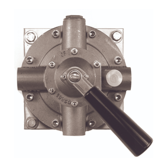
Millennium/Infinity Edition Important Note Steamix 203 has been in production since 1990 and there are three production editions. The "Classic" edition was manufactured from 1990 until 1999. The "Millennium" edition was manufactured from 1999 until 2003. The "Infinity" edition commenced manufacturing in January 2004 and is the current production model. Please review the Millennium/Infinity Edition (below) or Classic Edition (page 20) to identify the unit you own. Millennium Identification 1. Locate the serial number on the valve. Millennium valves have the serial number located on the body assembly and begin with the letters A-L. The serial numbers will be A-L10000 ó A-L13300 or higher and will have the identifier Steamix 203 in between a red and blue arrow directly after the serial number. 2. The Millennium edition has the number D2892 cast in raised digits on the underside of the steam inlet (left). Infinity Identification 1. Locate the serial number on the valve. Infinity valves have the serial number located on the body assembly and begin with the letters A-L. The serial numbers will be 13,300 or higher. 2. The Infinity edition has the number D4352 cast in raised digits on the underside of the steam inlet (left). Note: Millennium and Infinity valves share common replacement parts. Product Maintenance Millennium / Infinity The Steamix 203's Millennium/Infinity design incorporates simple and rugged construction so that with minimal routine care and operation within the specified limits, it should operate trouble free for long periods of time. All the mixing valve parts are field replaceable using standard tools. Periodic Inspection and Servicing 1. The following should be performed at intervals of one to six months depending on usage and condition of water (hard, soft, acidic or alkaline). a. Evenly tighten the two gland plate set screws to prevent leakage through the gland seal. b. Disassemble the mixing valve and clean internal parts with a good quality commercial inhibited de-scaler. - Page 15 Mixing Valve Disassembly Tools required, all available from Armstrong 1. Socket 1-1/2" 2. Allen key 5/32" 3. Allen key 3/16" 4. Allen key 1/4" 5. Open end wrench 1" 6. Assorted flat head screwdrivers Disassemble the mixing valve in a front to back sequence. Start at the temperature control lever and work towards the base. 1. Shut off the steam and water supplies. 2. Open the outlet shut-off valve and hose nozzle (if equipped) to relieve pressure. 3. Remove the temperature regulating lever by unscrewing the retaining screw and washer (these items may have been previously removed if temperature setting is locked). 4. Remove the gland plate screws and gland plate. 5. Sequentially remove the six retaining screws from the spring loaded bonnet. Maintain pressure against the bonnet while disassembling.
- Page 16 Diaphragm Replacement 1. When replacing the diaphragm it is considered good maintenance practice to check over/audit the complete Mixing Valve. 2. To replace the diaphragm, disconnect the Mixing Valve from the pipework. 3. Using a diagonal sequence, remove the eight valve body retaining screws. 4. Carefully separate the base from the body. Be careful not to misplace the connecting tube and "O" ring. Note: The diaphragm assembly may remain attached to either the base or body. Carefully remove it. 5. Withdraw the diaphragm assembly and inspect for damage. Replace if necessary. 6. If desired, the base, valve body and diaphragm piston may be descaled. Do not allow descaler to come in contact with the diaphragm. Caution: Use only silicone based lubricants when assembling the mixing valve. 7. Re-assemble in the reverse order. Ensure that both the base "O" ring and the connecting tube and the connecting tube "O" ring seat properly. Tighten screws diagonally opposite. Press the triangular spindle that is visible in the top of the valve body to check for free and even movement of the diaphragm assembly. Water Flow Regulator Disassembly Water Flow Regulator 1. Shut off the steam and water supplies. 2. Open the outlet shut off valve and nozzle (if equipped). 3. Remove the water flow regulator cap using 3/32" hex key on set screw. 4. Using a 1" wrench remove the water flow regulator assembly. 5. Remove the retaining clip and unscrew the spindle. 6. Replace worn o-rings and lubricate! 7. Re-assemble in reverse order. 8.
-
Page 17: Locking The Unit
Locking the Unit Installation Instructions for Tamper Resistant Locking Device Figure 1. Tools required: Flat blade screwdriver, Part #042 Locking Device (includes required 3/16" hex key), 3/32" Hex key (supplied with Steamix Valve/Hose Station). Figure 2. The cold water regulator is supplied as standard with a locking cap, which can be removed for "fine tune" mode. Locking cap is secured with a set screw and requires a 3/32" hex key for removal. Figure 3. Adjust the Mixing Valve on site to the desired outlet temperature set point (refer to pages 9-10 "Start Up Procedure"). Once adjusted and operating satisfactorily, remove and store the temperature control lever. Figure 4. Install the locking device and secure the 1/4-20 Hex Socket Head Bolt with the 3/16" Hex Key provided. Once the Steamix has been set on site and the locking device has been installed the user will only be able to operate the on/off flow control lever. The installation is now complete and the Steamix 203 must be tested for acceptable temperature and flow prior to being placed into service. The hex keys provided are not commonly available to plant cleanup personnel. Any subsequent tampering might be regarded by management as premeditated vandalism. Figure 1. Figure 2. Figure 3. Figure 4. - Page 18 Millennium/Infinity Edition When ordering spare parts, please include the valve serial number (located on assembly label), part number and part name. STEAMIX 203 Mixing Valve Millennium/Infinity Edition Spare Parts Component Component Part Description Alternate Kits ID Code Number / Suggested Kit # Temperature Control Lever Retaining Screw, Lock Washer and Flat Washer Temperature Control Lever Gland Plate Retaining Screw (2) Gland Plate 036-203-535 Gland Packing Temperature Control Spindle 036-203-590 Bonnet Retaining Screw (6) Bonnet 036-203-630 Upper Gasket M3, M4, M7, M8 Return Spring Poppet Valve Steam Diffuser Diffuser Copper Gasket M5, M7, M8 Cover Screw (8) 036-203-570 Body Consult Factory Water Flow Regulator Assembly Diaphragm Assembly Diaphragm Only Cover O-Seal M7, M8 Connecting Tube M7, M8 Connecting Tube O-Seal M7, M8...
- Page 19 Kits for Millennium/Infinity Edition M1 - Part # 036-203-525 M6 - Part # 036-203-580 Lever Handle Assembly 203 Water Flow Regulator Assembly 1- Temperature Control Retaining 16- Water Flow Regulator Assembly Screw, Lock Washer, Flat Washer Water Flow Regulator Spindle 2- Temperature Control Lever O-Seals (2) M2 - Part # 036-203-560 24- Water Flow Regulator Copper Upper Screw Pack Gasket Temperature Control Retaining M7 - Part # 036-203-510 Screw, Lock Washer, Flat Washer Diaphragm Assembly & Service Pack 3- Gland Plate Retaining Screw (2) Kit includes fully assembled 7- Bonnet Retaining Screw (6) diaphragm, piston, and upper and M3 - Part # 203-937-85 lower diaphragm retaining plates Bonnet Assembly Retrofit (item 17 on drawing). Includes Kit M5, Service Kit 203 listed above. Temperature Control Retaining M8 - Part # 036-203-515 Screw, Lock Washer, Flat Washer Diaphragm & Service Pack 2- Temperature Control Lever Kit includes diaphragm (item 18 on ...
- Page 20 The Steamix 203's Classic design incorporated simple and rugged construction so that with minimal routine care and operation within the specified limits it should operate trouble free for long periods of time. All the mixing valve parts are field replaceable using standard tools. However, some internal components have been superceded by parts kits common to the Millennium valve. Refer to substitution detail on pages 21. Periodic Inspection and Servicing 1. The following should be performed at intervals of one to six months depending on usage and condition of water (hard, soft, acidic or alkaline). a. Evenly tighten the two gland plate set screws to prevent leakage through the gland seal. b. Disassemble the mixing valve and clean internal parts with a good quality commercial inhibited de-scaler. c. Inspect all valve seats for wear, seals and gaskets for nicks or tears and check the condition of the diaphragm. d. Lubricate all moving parts with a high quality silicone based lubricant only. Mixing Valve Disassembly Tools required, all available from Armstrong Hot Water Group: 1. Socket 36mm 2. Allen key 3. Allen key 4. Allen key 5. Open end wrench 24mm 6. Assorted flat head screwdrivers...
- Page 21 Disassemble the mixing valve in a front to back sequence. Start at the temperature control lever and work towards the base. 1. Shut off the steam and water supplies. 2. Open the outlet shut-off valve and hose nozzle (if equipped) to relieve pressure. 3. Remove the temperature regulating lever by unscrewing the retaining screw and washer (these items may have been previously removed if temperature setting is locked). 4. Remove the gland plate screws and gland plate. 5. Sequentially remove the six retaining screws from the spring loaded bonnet. Maintain pressure against the bonnet while disassembling. 6. Remove the bonnet and spindle assembly. 7. Unscrew the spindle in a clockwise direction and remove from the bonnet. 8. Carefully push out the gland seal packing. 9. Carefully remove the spring and poppet valve from body. 10. Using a 36mm socket remove the diffuser and gasket. 11. Inspect the condition of the diffuser seat and replace if damaged. The diffuser may be de-scaled using a commercial inhibited descalent. Caution: Do Not twist the poppet when removing or damage to the diaphragm may occur. Note: Replace the poppet valve and spring as a single unit when damaged. This completes the disassembly of the upper section of the Mixing Valve. To clean or inspect the lower section of the Mixing Valve or if the Diaphragm requires replacement continue with the disassembly procedure in the next section (Diaphragm Replacement). Replace worn or damaged parts as required. Always replace "O" rings and gaskets with new ones after disassembly. (Use Service Pack #203-937-52.) Diaphragm Replacement 1. When replacing the diaphragm it is considered good maintenance practice to check over/audit the complete Mixing Valve. 2. To replace the diaphragm disconnect the Mixing Valve from the pipework.
- Page 22 Water Flow Regulator 1. Shut off the steam and water supplies. 2. Open the outlet shut off valve and nozzle (if equipped). 3. Remove the water flow regulator cap. 4. Using a 24mm wrench remove the water flow regulator assembly. 5. Remove the retaining clip and unscrew the spindle. 6. Replace worn o-rings and lubricate! Note: This drawing shows the Water Flow 7. Re-assemble in reverse order. Regulator Assembly M6 (part# 036-203-580) which is common to both Classic and Millennium 8. Check for leaks. editions. Water flow regulators on existing Classic valves will have a black plastic cap. 9. Perform initial temperature start-up procedures on pages 9-10. Tamper Resistant Locking Set Option Part No. 042R Note: Millennium Valve part number 042 cannot be retrofitted onto a Classic valve unless the complete Bonnet Assembly (Kit M3 part 203-937-58) and Water Flow Regulator (Kit M6 part 036-203-580) are first installed. This complete assembly becomes part number 042R (retrofit). 042R Component List Quantity Item Temperature Regulating Locking Device 1/4" - 20 x 7/8( Socket Head Cap Screw (SHCS) 5/32" Hex Key Cold water regulator with locking cap (M6 Part 036-203-580) Bonnet Assembly (M3 Part 203-937-58)
- Page 23 Complete the locking procedure as follows: Fig. 1. Tools required: Flat blade screwdriver, Part #042 Locking Device (includes required 3/16" hex key), 3/32" Hex key (supplied with Steamix Valve/Hose Station). Fig. 2. The Cold Water Regulator is supplied as standard with a locking cap, which can be removed for "fine tune" mode. Locking Cap is secured with a set screw and requires a 3/32" hex key for removal. Fig. 3. Adjust the Mixing Valve on site to the desired outlet temperature set point. Once adjusted and operating satisfactorily, remove and store the Temperature Control Lever. Fig. 4. Install the Locking Device and secure the 1/4-20 Hex Socket Head Bolt with the 3/16 Hex Key provided. Figure 1. Figure 2. Figure 3. Figure 4. Once the Steamix has been set on site and the locking device has been installed the user will only be able to operate the on/off flow control lever. The installation is now complete and the steamix 203 must be tested for acceptable temperature and flow prior to being placed into service. The Hex Keys provided are not commonly available to plant cleanup personnel. Any subsequent tampering might be regarded by management as premeditated vandalism. Warning: This product is designed to heat water for industrial washdown, vessel filling and process applications only. Access to extreme water temperatures and flash steam is a possibility. To avoid serious injury use extreme care and wear protective gloves, garments and safety glasses at all times.
- Page 24 Classic Edition Warning: Highlighted components are no longer available due to a design upgrade. Replacement Kits which feature new parts have been assembled and include all the components required to correctly replace the original part on your Classic edition Steamix. Please include the valve serial number, part number and part name. Component Component Part Description ID Code Number / Suggested Kit # 003-21 Base Consult Factory 012-03 Bonnet Assembly 236-10 Gland Plate 801-31 Body Consult Factory 856-26 Handle (temperature control lever) 196-07 Flow Regulator Cap 937-50 Diffuser Pack 937-51 Poppet Valve Pack A 937-52 Service Pack B 203-937-52 937-53 Upper Screw Pack C 203-937-53 937-54 Lower Screw Pack D 203-937-54 937-55 Diaphragm Assembly and Service Kit 203-937-55 937-56 Water Flow Regulator Assembly 937-57...
- Page 25 Kits for Classic Edition M1Part # 203-937-57 Part # 203-937-85 Connecting Tube Kit Bonnet Assembly Retrofit M3* Connecting Tube Temperature Control Retaining . M2Part # 203-937-82 Screw, Lock Washer, Flat Washer Diaphragm Temperature Control Lever Kit includes diaphragm only and Part Gland Plate Retaining Screw (2) 203-937-52 Service Kit. Installer must Upper Gasket clean and reuse existing piston and Gland Plate upper and lower diaphragm retaining Gland Packing plates. Temperature Control Spindle M3Part # 203-937-55 Bonnet Retaining Screw (6) Diaphragm Assembly Bonnet Kit includes fully assembled diaphragm, M4* - Part # 036-203-540 piston, and upper and lower diaphragm Diffuser/Poppet Valve Pack retaining plates as shown below (part# Upper Gasket 937-55). Kit includes Part 203-937-52 Return Spring Service Kit. Poppet Valve M4Part # 203-937-52 Steam Diffuser Service Kit 203 Steam Diffuser Copper Gasket Gland Packing M6* - Part # 036-203-580 Diffuser Copper Gasket Water Flow Regulator Assembly...
- Page 26 Standards and Approvals Armstrong International, Inc. is an ISO 9001 certified manufacturer. Armstrong International, Inc. maintains Canadian Registration Numbers specific to Steamix 203 on file.
- Page 27 Always check and be aware of the last set position of the temperature control handle before use. The Mixing Valve will automatically rise to the previous temperature setting unless the temperature control handle is returned to its seating position by rotating ìclockwiseî to stop. Always check that the Maximum Temperature Lockout feature has not been tampered with or mis-adjusted before use. Always wear water and heat protective gloves, garments, face protection, and safety glasses. Only to be operated by persons trained in this equipmentís use and safety. 10. Always return the hose to its holder after use. 11. Always release the water pressure in the hose after use. 12. Always close (shut off) the inlet supply controls after use. 13. Only use this equipment for its intended industrial purpose: washdowns, vessel filling, and process applications. 14. Do not substitute any component part on this assembly. 15. Use only performance matched parts for replacement from the Armstrong Hot Water Group. 16. Use of incorrect parts could cause serious personal injury. 17. Do not use attachments not authorized by the manufacturer. They may cause fire, electrical shock, or injury. 18. Do not operate the equipment if it malfunctions, is dropped, or has been damaged in any manner. 19. Do not operate this equipment if its hose is ripped or damaged in any manner. 20. Make certain that this equipment is properly installed before use. 21. Do not under any circumstances use this product to supply hot water for human showering, bathing, or hand washing applications. 22. This product is unsuitable for use to supply water at any temperature for drench showers, eye wash stations or other emergency equipment. 23. If you have questions, consult this manual or call our Customer Hotline at 1-(888)-HOT-HOSE. Steamix is a registered trademark of Armstrong Hot Water, a division of Armstrong International, Inc. Steamix is a brand of patented steam/water mixing valves and hose stations. For the purposes of this product manual, the model number Steamix 203 refers to both the Mixing Valve and Mixing Unit as individual products and the Mixing Unit featured on the Steamix Hose...
-
Page 28: Limited Warranty And Remedy
ITED TO, ANY IMPLIED WARRANTY OF MERCHANTABILITY OR ANY IMPLIED WARRANTY OF FITNESS FOR A PARTICULAR PURPOSE. The sole and exclusive remedy with respect to the above limited warranty or with respect to any other claim relating to the products or to defects or any condition or use of the products supplied by Armstrong, however caused, and whether such claim is based upon warranty, contract, negligence, strict liability, or any other basis or theory, is limited to Armstrongís repair or replacement of the part or product, excluding any labor or any other cost to remove or install said part or product, or at Armstrongís option, to repayment of the purchase price. As a condition of enforcing any rights or remedies relating to Armstrong products, notice of any warranty or other claim relating to the products must be given in writing to Armstrong: (i) within 30 days of last day of the applicable warranty period, or (ii) within 30 days of the date of the manifestation of the condition or occurrence giving rise to the claim, whichever is earlier. IN NO EVENT SHALL ARMSTRONG BE LIABLE FOR SPECIAL, DIRECT, INDIRECT, INCIDENTAL OR CONSEQUENTIAL DAMAGES, INCLUDING, BUT NOT LIMITED TO, LOSS OF USE OR PROFITS OR INTER- RUPTION OF BUSINESS. The Limited Warranty and Remedy terms herein apply notwithstanding any contrary...
Need help?
Do you have a question about the Steamix VE-M and is the answer not in the manual?
Questions and answers