Advertisement
Table of Contents
- 1 Installation Instructions
- 2 Typical Single Stage Reduction Installation (for Steam)
- 3 Start-Up and Adjustment Procedures
- 4 Disassembly
- 5 Assembly
- 6 Main Valve Kits
- 7 Main Diaphragm Kits
- 8 Gasket Sets
- 9 Adapter Kits
- 10 Troubleshooting Guide
- 11 Remote Mount Pilot Tubing N Assembly Instructions
- 12 New Tubing Set-Up
- 13 Notes
- Download this manual
Typical Single Stage Reduction Installation (For Steam)
Integral Mount
Globe
Valve
Armstrong
Strainer
Minimum of 10 Inlet
Pipe Diameters from
PRV to First Turn
Armstrong
TVS-Trap
This bulletin should be used by experienced personnel as a guide to the installation of the Model GP-2000 Pressure
Reducing Valve. Selection or installation of equipment should always be accompanied by competent technical
assistance. You are encouraged to contact Armstrong International, Inc. or its local sales representative for additional
information.
1. An Armstrong Inverted Bucket Steam Trap is recom-
mended to drain the condensate at the inlet of the
PRV.
2. An Armstrong 100 mesh Y-Strainer should be installed
before the PRV to reduce the chance of dirt fouling.
3. Pressure gauges should be installed before and after
the PRV. The downstream gauge should be installed in
or near the control pipe.
4. Control pipe connections go into ºî tapping on the
side of the pilot valve. Be certain the pipe is pitched
away from the PRV to drain condensate away from
pilot. Erratic control could result if this is not done.
Control pipe length should be a minimum of 10 outlet
pipe diameters from the last tee, elbow or fitting.
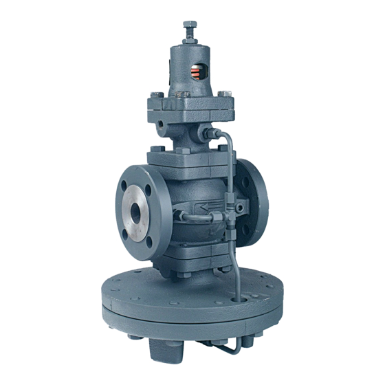
Pressure Reducing Valve
Integral and Remote Pilot
Installation, Operation and Maintenance
Minimum of 10 Outlet
Pipe Diameters from
Last Valve or Fitting
By-Pass
Control Pipe
Gate
(Pitch Down)
Valve
GP-2000
Minimum of 20 Outlet
Pipe Diameters from
PRV to First Turn
Note:
Safety Relief Valve to be set at
10 psi higher or 10% higher than
the downstream pressure, whichever
is greater.
Installation Instructions
Model GP-2000
Remote Mount
Globe
Safety Relief
Valve
Minimum of 10 Inlet
Pipe Diameters from
PRV to First Turn
Armstrong
TVS Trap
Note:
Safety Relief Valve to be set at
10 psi higher or 10% higher than
the downstream pressure, whichever
is greater
5. If a bypass line is needed to allow system operation
while the valve is being serviced then install a quality
globe valve on the bypass line. Leaking valves will
cause system problems.
6. Piping immediately downstream of PRV should be
expanded to accommodate low-pressure expansion
through a PRV. Approximately 6,000 ñ 12,000 FPM
maximum velocity.
7. Install the PRV with diaphragm chamber down and
with flow in the direction of the arrow on the body.
8. Do not install a quick opening or quick closing valve on
the downstream side of the PRV. This can cause
erratic pressure control and cause safety relief valves
to discharge.
Minimum of 10 Outlet
Valve
By-Pass
Armstrong
Strainer
GP-2000
Minimum of 20 Outlet
Pipe Diameters from
PRV to First Turn
Armstrong
TVS Trap
Bulletin No. AY-712-C
Pipe Diameters from
Last Valve or Fitting
Safety Relief
Valve
Advertisement
Table of Contents

Related Manuals for Armstrong GP-2000


Summary of Contents for Armstrong GP-2000
- Page 1 This bulletin should be used by experienced personnel as a guide to the installation of the Model GP-2000 Pressure Reducing Valve. Selection or installation of equipment should always be accompanied by competent technical assistance. You are encouraged to contact Armstrong International, Inc. or its local sales representative for additional information.
- Page 2 Start-Up and Adjustment Procedures Improper sizing or adjustment of the pressure reducing valve may cause hunting, scale problems, water hammer, etc. and can heavily damage the main parts of the valve. Adjust the valve as follows: 1. Close the gate valves before and after the pressure 5.
- Page 3 Start-Up and Adjustment Procedures Adapter Kits Main Valve Kits Main Diaphragm Kits Gasket Sets OB-2000 and OB-2000PT K-2100 thru K-2108 K-2130 thru K-2136 K-2380 thru K-2386 K-2020 thru K-2036 1 Main Valve 2 Main Diaphragms 1 Screen All external tubing and fittings Æ...
- Page 4 Troubleshooting Guide Before working on the valve, make sure that the inlet strainer is clean, bypass valve is closed and upstream and downstream pressure gauges are working properly. Refer to Figure 3-1. Problem Cause Test Solution Outlet Inlet pressure is not adequate for Maximum outlet pressure is 85% of the inlet with a Raise inlet pressure if possible.
- Page 5 2. Remove the ºî plug on the inlet side of the main valve body (1) (for GP-2000 remote mount pilot and OB-2000 temperature pilot) with an allen wrench. 3. Thread the ºî long nipple (4) into the main valve body (1) (in place of the ºî...
- Page 6 New Tubing Set-Up The external tubing for our GP-2000 and OB-2000 series New Type Tubing has been modified to enhance the performance of these Figure 6-1 models. The following explains the difference between the old and new tubing assembly. It is important to have these fittings in the correct location in order to get optimum performance from these valves.
- Page 7 Notes...
- Page 8 Armstrong Pressure/Temperature Controls Group, 221 Armstrong Blvd., P.O. Box 408, Three Rivers, Michigan 49093 - USA Ph: (269) 279-3600 Fax: (269) 273-8656 www.armstrong-intl.com Bulletin AY-712-C 10/02 Printed in U.S.A.
Need help?
Do you have a question about the GP-2000 and is the answer not in the manual?
Questions and answers