
Related Manuals for WIKA F-20


Summary of Contents for WIKA F-20
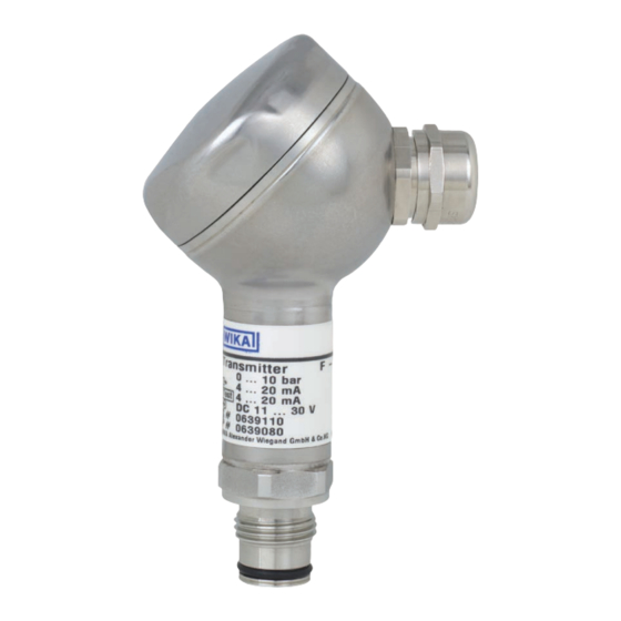
- Page 1 Operating instructions Betriebsanleitung Pressure transmitter, models F-20 and F-21 Druckmessumformer, Typen F-20 und F-21 Pressure transmitter models F-20, F-21...
- Page 2 Betriebsanleitung Typen F-20 und F-21 Seite 17 - 31 © 2012 WIKA Alexander Wiegand SE & Co. KG All rights reserved. / Alle Rechte vorbehalten. WIKA ® is a registered trademark in various countries. WIKA ® ist eine geschützte Marke in verschiedenen Ländern.
-
Page 3: Table Of Contents
Contents Contents 1. General information 2. Function 3. Safety 4. Packaging 5. Starting, operation 6. Specifications 7. Adjustment of zero point / span 8. Maintenance 9. Trouble shooting 10. Storage, disposal WIKA operating instructions pressure transmitters, models F-20, F-21... -
Page 4: General Information
The supply current is the measurement signal. 3-wire Two connection lines are intended for the voltage supply. One connection line is intended for the measurement signal. Positive supply connection Negative supply connection Positive measurement connection WIKA operating instructions pressure transmitters, models F-20, F-21... -
Page 5: Function
2. Function / 3. Safety 2. Function F-20: Pressure connection with internal diaphragm (standard version). F-21: Pressure connection with flush diaphragm for highly viscous or solids entrained media which might clog the pressure port. The pressure prevailing within the application is transformed into a standardised electrical signal through the deflection of the diaphragm, which acts on the sensor element with the power supply fed to the transmitter. - Page 6 Take precautions with regard to remaining media in removed pressure transmitter. Remaining media ■ in the pressure port may be hazardous or toxic! Have repairs performed by the manufacturer only. ■ Open circuit before removing connector / cover. ■ WIKA operating instructions pressure transmitters, models F-20, F-21...
-
Page 7: Packaging
Use the pressure transmitter only if the diaphragm is undamaged. ■ Use the pressure transmitter only if it is in a faultless condition as far as the safety-relevant features ■ are concerned. WIKA operating instructions pressure transmitters, models F-20, F-21... - Page 8 Test DC 11 ... 30 V Power Supply S# 0639110 Serial No. P# 0639080 Product No. Coded manufacture date Made in Germany WIKA Alexander Wiegand SE & Co. KG 63911 Klingenberg WIKA operating instructions pressure transmitters, models F-20, F-21...
- Page 9 Remove the protection cap only just before installation and absolutely avoid any damage to the ■ diaphragm during installation as well (F-21). For Model F-20 you have to provide for a sealing element; exceptions are instruments with ■ self-sealing threads (e.g. NPT thread). For Model F-21 the sealing is included in delivery.
- Page 10 By means of the test circuit the current can be metered during normal operation without having to disconnect the instrument. For that purpose you have to connect an ammeter (internal resistance < 15 Ohm) to the test +/- terminals. WIKA operating instructions pressure transmitters, models F-20, F-21...
-
Page 11: Specifications
≤ {0.25} for measuring ranges ≥ 0.25 bar Non-linearity % of ≤ 0.2 (BFSL) according to IEC 61298-2 span Non-repeatability % of ≤ 0.1 span 1-year stability % of ≤ 0.2 (at reference conditions) span WIKA operating instructions pressure transmitters, models F-20, F-21... - Page 12 (e.g. transmitting device, radio equipment), or use sheath current filters where applicable. When designing your plant, take into account that the stated values (e.g. over pressure safety) apply depending on the material, thread and sealing element used. WIKA operating instructions pressure transmitters, models F-20, F-21...
-
Page 13: Adjustment Of Zero Point / Span
If the zero point is incorrect, repeat procedure as required. ■ Reassemble the instrument carefully. ■ Make sure all sealings and o-rings are not damaged and correctly installed to assure the rated moisture ingress protection. ■ WIKA operating instructions pressure transmitters, models F-20, F-21... -
Page 14: Maintenance
Remove the pressure transmitter from service and mark it to prevent it frombeing used again ■ accidentally, if it becomes damaged or unsafe for operation. Have repairs performed by the manufacturer only. ■ WIKA operating instructions pressure transmitters, models F-20, F-21... - Page 15 *) Make sure that after the setting the unit is working properly. In case the error continues to exist send in the instrument for reparation (or replace the unit). If the problem persists, contact our sales department. WIKA operating instructions pressure transmitters, models F-20, F-21...
-
Page 16: Storage, Disposal
In this case, contact the manufacturer. USA, Canada If the problem continues, contact WIKA or an authorized agent for assistance. If the pressure transmitter must be returned obtain an RMA (return material authorization) number and shipping instructions from the place of purchase. - Page 17 Inhalt Inhalt 1. Allgemeines 2. Funktion 3. Sicherheit 4. Verpackung 5. Inbetriebnahme, Betrieb 6. Technische Daten 7. Einstellung Nullpunkt / Spanne 8. Wartung 9. Störbeseitigung 10. Lagerung, Entsorgung WIKA Betriebsanleitung Druckmessumformer, Typen F-20, F-21...
-
Page 18: Allgemeines
Fax: +49 9372 132-406 info@wika.de Abkürzungen 2-Leiter Zwei Anschlussleitungen dienen zur Spannungsversorgung. Der Speisestrom ist das Mess-Signal. 3-Leiter Zwei Anschlussleitungen dienen zur Spannungsversorgung. Eine Anschlussleitung dient für das Mess-Signal. Positiver Versorgungsanschluss Negativer Versorgungsanschluss Positiver Messanschluss WIKA Betriebsanleitung Druckmessumformer, Typen F-20, F-21... -
Page 19: Funktion
2. Funktion / 3. Sicherheit 2. Funktion F-20: Druckanschluss mit innenliegender Membran (Standardausführung). F-21: Druckanschluss mit frontbündiger Membrane für hochviskose oder kristallisierende Medien, die die Bohrung des Druckanschlusses zusetzen können. Mittels Sensorelement und unter Zuführung von Hilfsenergie wird über die Verformung einer Membran der anstehende Druck in Ihrer Anwendung in ein verstärktes standardisiertes elektrisches Signal umgewandelt. - Page 20 Ergreifen Sie Vorsichtsmaßnahmen für Messstoffreste in ausgebauten Druckmessgeräten. ■ Messstoffreste können zur Gefährdung von Menschen, Umwelt und Einrichtung führen! Lassen Sie Reparaturen nur vom Hersteller durchführen. ■ Öffnen Sie den Stromkreis, bevor Sie den Stecker / Deckel abnehmen. ■ WIKA Betriebsanleitung Druckmessumformer, Typen F-20, F-21...
-
Page 21: Verpackung
Untersuchen Sie das Druckmessgerät auf eventuell entstandene Transportschäden. Sind offensichtlich Schäden ■ vorhanden, teilen Sie dies dem Transportunternehmen und WIKA unverzüglich mit. Bewahren Sie die Verpackung auf, denn diese bietet bei einem Transport einen optimalen Schutz (z. B. wechselnder ■... - Page 22 4 ... 20 mA Anschlussbelegung Testkreisanschluss 4 ... 20 mA Test DC 11 ... 30 V Spannungsversorgung S# 0639110 Serien-Nr. P# 0639080 Erzeugnis-Nr. Codiertes WIKA Alexander Wiegand SE & Co. KG 63911 Klingenberg Made in Germany Herstelldatum WIKA Betriebsanleitung Druckmessumformer, Typen F-20, F-21...
- Page 23 Entfernen Sie die Schutzkappe erst kurz vor dem Einbau und achten Sie unbedingt darauf, dass die ■ Membran auch während des Einbaus nicht beschädigt wird (F-21). Bei Typ F-20 müssen Sie eine Dichtung vorsehen; Ausnahme sind Geräte mit selbstdichtendem ■ Gewinde (z. B. NPT-Gewinde). Bei Typ F-21 ist der Dichtring im Lieferumfang enthalten.
- Page 24 Funktion des Testkreises für 2-Leiter Anhand des Testkreises ist es möglich, während des normalen Betriebes eine Strommessung durchzuführen ohne das Gerät abzuklemmen. Sie müssen hierzu ein Amperemeter (Innenwiderstand < 15 Ohm) an die Klemmen Test +/- anschließen. WIKA Betriebsanleitung Druckmessumformer, Typen F-20, F-21...
-
Page 25: Technische Daten
% d. Spanne ≤ 0,2 (bei Referenzbedingungen) Zulässige Temperaturbereiche Messstoff °C -30 ... +100 {-40 ... +125} ■ Umgebung °C -20 ... +80 {-30 ... +105} ■ Lagerung °C -40 ... +100 ■ Nenntemperaturbereich °C 0 ... +80 WIKA Betriebsanleitung Druckmessumformer, Typen F-20, F-21... - Page 26 Das Ausgangssignal muss sich dem anstehenden Druck proportional verhalten. Wenn dies nicht so ist, kann das ein Hinweis auf eine Beschädigung der Membran sein. Lesen Sie in diesem Fall in Kapitel 9 „Störbeseitigung“ nach. WIKA Betriebsanleitung Druckmessumformer, Typen F-20, F-21...
-
Page 27: Einstellung Nullpunkt / Spanne
Wenn der Nullpunkt nicht stimmt ggf. Prozedur wiederholen. ■ Schließen Sie das Druckmessgerät wieder sorgfältig. Achten Sie darauf, dass die Dichtungen unbeschädigt und ■ sauber sind und auf die korrekte Lage der Dichtungen, um die Schutzart zu gewährleisten. WIKA Betriebsanleitung Druckmessumformer, Typen F-20, F-21... -
Page 28: Wartung
Messstoffreste können zur Gefährdung von Menschen, Umwelt und Einrichtung führen! Setzen Sie das Druckmessgerät außer Betrieb und schützen Sie es gegen versehentliche ■ Inbetriebnahme, wenn Sie Störungen nicht beseitigen können. Lassen Sie Reparaturen nur vom Hersteller durchführen. ■ WIKA Betriebsanleitung Druckmessumformer, Typen F-20, F-21... - Page 29 Ausfall Rücksprache mit Hersteller *) Signalspanne schwankend EMV-Störquellen in Umgebung, z. B. Frequenzumrichter Gerät abschirmen; Leitungsabschirmung; Störquelle entfernen Abweichendes Nullpunkt- Membranbeschädigung, z. B. durch Schläge, Gerät austauschen Signal abrasives/agressives Medium; Korrosion an Membran/ Druckanschluss WIKA Betriebsanleitung Druckmessumformer, Typen F-20, F-21...
- Page 30 Eine solche Erklärung beinhaltet alle Materialien, welche mit dem Gerät in Berührung kamen, auch solche, die zu Testzwecken, zum Betrieb oder zur Reinigung eingesetzt wurden. Das Rücksendeformular ist über unsere Internet- Adresse (www.wika.de / www.wika.com) verfügbar. WIKA Betriebsanleitung Druckmessumformer, Typen F-20, F-21...
-
Page 31: Lagerung, Entsorgung
Montieren Sie die Schutzkappe bei Lagerung des Druckmessgerätes, damit die Membran nicht beschädigt wird (F-21). Entsorgung Entsorgen Sie Gerätekomponenten und Verpackungsmaterialien entsprechend den einschlägigen landesspezifischen Abfallbehandlungs- und Entsorgungsvorschriften des Anliefergebietes. Nicht mit dem Hausmüll entsorgen. Für eine geordnete Entsorgung gemäß nationaler Vorgaben sorgen. WIKA Betriebsanleitung Druckmessumformer, Typen F-20, F-21... - Page 32 WIKA subsidiaries worldwide can be found online at www.wika.com. WIKA Niederlassungen weltweit finden Sie online unter www.wika.de. WIKA Alexander Wiegand SE & Co. KG Alexander-Wiegand-Strasse 30 63911 Klingenberg • Germany Tel. +49 9372 132-0 Fax +49 9372 132-406 info@wika.de www.wika.de...
Need help?
Do you have a question about the F-20 and is the answer not in the manual?
Questions and answers