Table of Contents
Advertisement
Available languages
Available languages
Quick Links
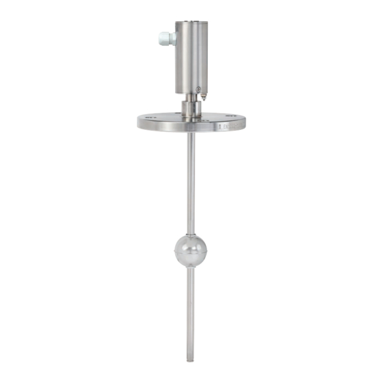
Magnetostrictive level transmitter for hazardous areas,
models FLM-CAI, FLM-TAI, BLM-TAI
Magnetostriktiv-Füllstandstransmitter für explosionsgefährdete
Bereiche, Typen FLM-CAI, FLM-TAI, BLM-TAI
Mounting flange, spherical float from stainless steel, model FLM-CAI
Operating instructions
Betriebsanleitung
EN
DE
Advertisement
Chapters
Table of Contents

Related Manuals for WIKA FLM-CAI


Summary of Contents for WIKA FLM-CAI
- Page 1 Operating instructions Betriebsanleitung Magnetostrictive level transmitter for hazardous areas, models FLM-CAI, FLM-TAI, BLM-TAI Magnetostriktiv-Füllstandstransmitter für explosionsgefährdete Bereiche, Typen FLM-CAI, FLM-TAI, BLM-TAI Mounting flange, spherical float from stainless steel, model FLM-CAI...
- Page 2 3 - 36 BLM-TAI (Ex) Betriebsanleitung Typen FLM-CAI, FLM-TAI, BLM-TAI Seite 37 - 70 (Ex) © 09/2019 WIKA Alexander Wiegand SE & Co. KG All rights reserved. / Alle Rechte vorbehalten. WIKA is a registered trademark in various countries. ® WIKA ist eine geschützte Marke in verschiedenen Ländern.
-
Page 3: Table Of Contents
Contents Contents 1. General information 2. Design and function 2.1 Description ......5 2.2 Model overview ..... . 6 2.3 Construction and principle of operation . - Page 4 10. Specifications 10.1 Model FLM-CAI ..... 10.2 Model FLM-TAI .....
-
Page 5: General Information
2. Design and function Description The model FLM-CAI (with guide tube Ø 6 mm) and model FLM-TAI (with guide tube Ø 12 mm) high-accuracy level transmitters are used for the continuous measurement of the level of liquid media in vessels. The measurement procedure used exploits the physical effect of magnetostriction and is largely independent of the temperature. -
Page 6: Model Overview
Device protection through intrinsic safety “i“ EN 60079-26:2015 Equipment of equipment protection level (EPL) Ga Model overview Model Guide tube diameter in mm Installation type FLM-CAI Direct installation FLM-TAI Direct installation BLM-TAI Bypass mounting Operating instructions magnetostrictive level transmitter, models FLM-xAI, BLM-TAI (Ex) -
Page 7: Construction And Principle Of Operation
2. Design and function Construction and principle of operation The construction of the level transmitter is illustrated in the version with screw-in body. In the probe head of the level transmitter are located the connection terminals and the adjustment buttons protected by the cover . The electrical connection is made via an M16 x 1.5 cable gland ... -
Page 8: Scope Of Delivery
2. Design and function The measurement procedure shown in the following figure exploits the physical effect of magnetostriction and is largely independent of the temperature. In the guide tube, a wire from magnetostrictive material is stretched. Via the sensor electronics, current pulses are sent through the wire, which generate a circular magnetic field . -
Page 9: Safety
3. Safety 3. Safety Explanation of symbols DANGER! ... indicates a directly dangerous situation resulting in serious injury or death, if not avoided. WARNING! ... indicates a potentially dangerous situation that can result in serious injury or death, if not avoided. CAUTION! ... -
Page 10: Improper Use
3. Safety The instrument has been designed and built solely for the intended use described here, and may only be used accordingly. The manufacturer shall not be liable for claims of any type based on operation contrary to the intended use. Improper use Improper use is defined as any application that exceeds the technical performance limits. -
Page 11: Personnel Qualification
3. Safety Personnel qualification WARNING! Risk of injury should qualification be insufficient Improper handling can result in considerable injury and damage to property. ▶ The activities described in these operating instructions may only be carried out by skilled personnel who have the qualifications described below. Skilled personnel Skilled personnel, authorised by the operator, are understood to be personnel who, based on their technical training, knowledge of measurement and control technology and on... -
Page 12: Labelling, Safety Marks
Art. No.: 3. Safety Tag. No.: 4 ... 20 mA max. DC 15 ... 30 V IP68 Labelling, safety marks WIKA Alexander Wiegand SE & Co. KG Alexander-Wiegand-Strasse 30 63911 Klingenberg Product label Level Sensor ??????? Type: ???-???????????????? ... -
Page 13: Transport, Packaging And Storage
3. Safety / 4. Transport, packaging and storage II 1G Ex ia IIC T6 ... T4 Ga II 1/2G Ex ia IIC T6 ... T4 Ga/Gb II 2G Ex ia IIC T6 ... T4 Gb II 1D Ex ia IIIC T160 °C Da Special conditions for use (X conditions) 1. -
Page 14: Commissioning, Operation
5. Commissioning, operation 5. Commissioning, operation DANGER! Danger to life from explosion! Through working in flammable atmospheres, there is a risk of explosion which can cause death. ▶ Only carry out set-up work in non-hazardous environments! DANGER! Risk of injury due to improper use Work on containers involves the danger of intoxication and suffocation. - Page 15 5. Commissioning, operation During mounting, ensure that the guide tube is not bent and that the float is not ■ subjected to shock loads. The installation of the level transmitter in areas with strong external magnetic fields is ■ not permitted, since this will impede the correct measured value determination. The level transmitter can also be installed in the vessel from below.
-
Page 16: Screw-In Body" Version
5. Commissioning, operation 5.1.1 “Screw-in body” version The dismounting of the float is then only required if the float cannot pass through the mounting hole in the vessel. Otherwise, only mounting steps 3, 6 and, if necessary, 7 must be carried out. Inserting the level transmitter into the vessel: 1. -
Page 17: Flange" Version
5. Commissioning, operation 5.1.2 “Flange” version The guide tube is firmly welded to the flange, so the insertion length cannot be changed. Secure the flange and the flange sealing with the flange screws and nuts. The screws, nuts and seals are the responsibility of the operator and should be chosen dependent upon the measuring medium. - Page 18 5. Commissioning, operation Mounting with bypass BLM for bypass Distance from guide tube to centre of float: max. distance depending on bypass float min. magnet position Guide tube, mounted free of tension (not deformed) Bypass tube Magnet position min. magnet position Bypass float Probe fixing...
-
Page 19: Electrical Connection
≤ 100 mA / 200 mA ≤ 1 W ▶ For further data, see the EC-type examination certificate at www.wika.com. 1) The permissible input current li depends on the ambient temperature T Make sure that the permissible external capacitance C... -
Page 20: Cable Length
5. Commissioning, operation 5.2.2 Cable length The maximum cable length is dependent upon the overall resistance, which is composed of the wiring resistance and the load of connected instruments (see chapter 5.2.1 “Connection diagram (Ex)”). The cable (length and cross-section) must be selected such that, in the event of the highest current supply (21.5 mA), the voltage does not drop below the probe-specific minimum supply voltage (8 V). -
Page 21: Wiring With Cable Gland
5. Commissioning, operation Example: Supply voltage: 12 V (±5 %) Supply voltage U = 11.4 V (12 V - 5 %) Minimum supply voltage U = 8 V Highest current supply I = 0.0215 A Load R = 86.8 Ω Cable resisatance R = 0.0356 Ω/m with cable cross-section Q = 0.5 mm²... -
Page 22: Wiring With M12 Connector
5. Commissioning, operation Removable screw terminal 3. Thread the 2-wire cable into the union nut and tighten (outer diameter: 5 … 10 mm). 4. Remove the screw terminal . 5. Connect the 2-wire cable to the poles marked with (+) and (–) on the screw terminal . 6. - Page 23 Black Pin 4 Pin 2 Pin 1 Pin assignment of the coupling of the WIKA connection cable Characteristic for connection cable between level transmitter and associated equipment: 2-wire, non-shielded cable ■ Blue or marked in blue (cable for intrinsically safe circuits) ■...
-
Page 24: Adjustment
5. Commissioning, operation Adjustment For variants with HART protocol, the settings described in the following can also be made ® conveniently remotely without having to open the probe head. 5.3.1 Measuring span on the level transmitter For the adjustment of the 4 mA and 20 mA points on the level transmitter, there are two buttons (... -
Page 25: Current Supply In Error Mode
5. Commissioning, operation 3. The level transmitter enters adjustment mode. The current supply of the level transmitter is 12 mA. Without pressing the button again, the level transmitter remains in adjustment mode for 20 seconds before it switches back to measuring mode without changing the adjustment. -
Page 26: Safety-Related Characteristic Values
5. Commissioning ... / 6. Safety-related characteristic values 3. To set a current supply of 3.6 mA, during the dwell time (10 seconds) in error mode, press the “4 mA” button ■ briefly (0.1 ... 2 seconds). of 21.5 mA, during the dwell time (10 seconds) in error mode, press the “20 mA” ■... - Page 27 6. Safety-related characteristic values The maximum temperatures for use in gas hazardous areas, depending on the temperature class and the category or equipment protection level, are indicated in temperature table 1: Temperature table 1: Operating temperatures of the level transmitters Temperature class Category 1G or equipment protection level Ga (complete level transmitter installed in zone 0) T6 (I...
-
Page 28: Faults
6. Safety-related characteristic values / 7. Faults The maximum ambient temperatures for use in gas hazardous areas, depending on the surface ambient temperature and the dust layer, are indicated in temperature table 2. Temperature table 2: Operating temperatures for dust hazardous areas Maximum surface temperature Ambient temperature T Dust layer ≤... - Page 29 7. Faults The following table contains the most frequent causes of faults and the necessary countermeasures. Faults Causes Measures No or undefined function Incorrect terminal assignment Compare connection diagram Insulation not clamped sufficiently Check the terminals Adjusting collar has slipped or is Check the location of the incorrectly fitted after the removal adjusting collar...
-
Page 30: Maintenance And Cleaning
8. Maintenance and cleaning 8. Maintenance and cleaning For contact details see chapter 1 “General information” or the back page of the operating instructions. Maintenance When used properly, the magnetostrictive level transmitters work maintenance-free. They must be subjected to visual inspection within the context of regular maintenance, however, and included in the vessel pressure test. -
Page 31: Dismounting
9. Dismounting, return and disposal 9. Dismounting, return and disposal WARNING! Physical injuries and damage to property and the environment through residual media Residual media in the dismounted instrument can result in a risk to persons, the environment and equipment. ▶... -
Page 32: Specifications
10. Specifications 10. Specifications 10.1 Model FLM-CAI Magnetostrictive level transmitter Guide tube Ø 6 mm (max. 1,000 mm) ■ Ø 12 mm (max. 3,000 mm) ■ Process connection Mounting thread downwards G 1/2 ... G 2 ■ 1/2 NPT ... 2 NPT ■... -
Page 33: Model Flm-Tai
10. Specifications 10.2 Model FLM-TAI Mounting thread Flange Electrical connection Sensor housing, material stainless steel 1.4301 Process connection Mounting thread downwards Mounting flange G 1 1/2 or G 2 DIN DN 50 ... DN 200, ■ PN 6 ... PN 100 ANSI 2"... -
Page 34: Model Blm-Tai
10. Specifications 10.3 Model BLM-TAI Specifications Stainless steel 1.4305, optionally stainless steel 1.4404 Connection housing (sensor housing) Sensor tube Stainless steel 1.4571, optionally stainless steel 1.4404 Tube Ø 12 mm, tube length L max. 6,000 mm Medium temperature -60 ... +450 °C Ambient temperature T4/T5/T6: -20 ... - Page 35 10. Specifications Material Version Description For guide tube Limit density Ø in mm 85 % in kg/m Buna (NBR) B20A Cylinder Ø 20 mm B23A Cylinder Ø 23 mm B25A Cylinder Ø 25 mm B30A Cylinder Ø 30 mm B40A Cylinder Ø...
-
Page 36: Annex: Eu Declaration Of Conformity
Annex: EU declaration of conformity Operating instructions magnetostrictive level transmitter, models FLM-xAI, BLM-TAI (Ex) - Page 37 Inhalt Inhalt 1. Allgemeines 2. Aufbau und Funktion 2.1 Beschreibung ..... . 2.2 Typenübersicht..... . 2.3 Aufbau und Funktionsweise .
- Page 38 10. Technische Daten 10.1 Typ FLM-CAI ..... . 10.2 Typ FLM-TAI ..... .
-
Page 39: Allgemeines De
LM 10.05 (BLM-TAI) 2. Aufbau und Funktion Beschreibung Die hochgenauen Füllstandstransmitter Typen FLM-CAI (mit Gleitrohr-Ø 6 mm) und FLM-TAI (mit Gleitrohr-Ø 12 mm) dienen zur kontinuierlichen Füllstandsmessung von flüssigen Medien in Behältern. Das angewandte Messverfahren nutzt den physikalischen Effekt der Magnetostriktion aus und ist weitgehend unabhängig von der Temperatur. Es findet besonders dort Anwendung, wo sehr exakte Füllstandsmessungen erforderlich sind,... -
Page 40: Typenübersicht
Das Gerät ist gemäß den folgenden europäischen Normen ausgeführt: EN IEC 60079-0:2018 Betriebsmittel – Allgemeine Anforderungen EN 60079-11:2012 Geräteschutz durch Eigensicherheit „i“ EN 60079-26:2015 Betriebsmittel mit Geräteschutzniveau (EPL) Ga Typenübersicht Gleitrohrdurchmesser in mm Einbauart FLM-CAI Direkteinbau FLM-TAI Direkteinbau BLM-TAI Bypassanbau Betriebsanleitung Magnetostriktiv-Füllstandstransmitter, Typen FLM-xAI, BLM-TAI (Ex) -
Page 41: Aufbau Und Funktionsweise
2. Aufbau und Funktion Aufbau und Funktionsweise Der Aufbau des Füllstandstransmitters ist abgebildet in der Ausführung mit Einschraubkör- per. Im Sondenkopf des Füllstandstransmitters befinden sich die durch den Deckel geschützten Anschlussklemmen und die Justiertasten. Der elektrische Anschluss erfolgt über eine M16 x 1,5-Kabelverschraubung ... -
Page 42: Lieferumfang
2. Aufbau und Funktion Das in der nachfolgenden Abbildung dargestellte Messverfahren nutzt den physikalischen Effekt der Magnetostriktion und ist weitgehend unabhängig von der Temperatur. Im Gleitrohr ist ein Draht aus magnetostriktivem Material gespannt. Durch die Sensorelekt- ronik werden Strompulse durch den Draht gesendet, die ein zirkulares Magnetfeld erzeugen. -
Page 43: Sicherheit
3. Sicherheit 3. Sicherheit Symbolerklärung GEFAHR! ... weist auf eine unmittelbar gefährliche Situation hin, die zum Tod oder zu schweren Verletzungen führt, wenn sie nicht gemieden wird. WARNUNG! ... weist auf eine möglicherweise gefährliche Situation hin, die zum Tod oder zu schweren Verletzungen führen kann, wenn sie nicht gemieden wird. -
Page 44: Fehlgebrauch
3. Sicherheit Das Gerät ist ausschließlich für den hier beschriebenen bestimmungsgemäßen Verwen- dungszweck konzipiert und konstruiert und darf nur dementsprechend verwendet werden. Ansprüche jeglicher Art aufgrund von nicht bestimmungsgemäßer Verwendung sind ausgeschlossen. Fehlgebrauch Als Fehlgebrauch gilt jede Verwendung, die die technischen Leistungsgrenzen überschreitet. WARNUNG! Verletzungen durch Fehlgebrauch Fehlgebrauch des Gerätes kann zu gefährlichen Situationen und Verletzungen... -
Page 45: Personalqualifikation
3. Sicherheit Personalqualifikation WARNUNG! Verletzungsgefahr bei unzureichender Qualifikation Unsachgemäßer Umgang kann zu erheblichen Personen- und Sachschäden führen. ▶ Die in dieser Betriebsanleitung beschriebenen Tätigkeiten nur durch Fachpersonal nachfolgend beschriebener Qualifikation durchführen lassen. Fachpersonal Das vom Betreiber autorisierte Fachpersonal ist aufgrund seiner fachlichen Ausbildung, seiner Kenntnisse der Mess- und Regelungstechnik und seiner Erfahrungen sowie Kennt- nis der landesspezifischen Vorschriften, geltenden Normen und Richtlinien in der Lage, die beschriebenen Arbeiten auszuführen und mögliche Gefahren selbstständig zu erkennen. -
Page 46: Beschilderung, Sicherheitskennzeichnungen
Ser. No.: Art. No.: 3. Sicherheit Tag. No.: 4 ... 20 mA max. DC 15 ... 30 V IP68 Beschilderung, Sicherheitskennzeichnungen WIKA Alexander Wiegand SE & Co. KG Alexander-Wiegand-Strasse 30 63911 Klingenberg Typenschild Level Sensor ??????? Type: ???-???????????????? ... -
Page 47: Transport, Verpackung Und Lagerung
3. Sicherheit / 4. Transport, Verpackung und Lagerung II 1G Ex ia IIC T6 ... T4 Ga II 1/2G Ex ia IIC T6 ... T4 Ga/Gb II 2G Ex ia IIC T6 ... T4 Gb II 1D Ex ia IIIC T160 °C Da Besondere Bedingungen für die Verwendung (X-Conditions) 1. -
Page 48: Inbetriebnahme, Betrieb
5. Inbetriebnahme, Betrieb 5. Inbetriebnahme, Betrieb GEFAHR! Lebensgefahr durch Explosion! Durch Arbeiten in entzündlichen Atmosphären besteht Explosionsgefahr, die zum Tod führen kann. ▶ Rüstarbeiten nur in nicht-explosionsgefährdeter Umgebung durchführen! GEFAHR! Verletzungsgefahr durch unsachgemäßes Arbeiten Beim Arbeiten an Behältern besteht Vergiftungs- oder Erstickungsgefahr. ▶... - Page 49 5. Inbetriebnahme, Betrieb Während der Montage darauf achten, dass das Gleitrohr nicht verbogen wird und dass ■ der Schwimmer keinen Stoßbelastungen ausgesetzt ist. Der Einbau eines Füllstandstransmitters in Bereichen mit starkem externem Magnetfeld ■ ist unzulässig, da hierdurch die korrekte Messwertermittlung behindert werden kann. Der Füllstandstransmitter kann auch von unten in den Behälter eingebaut werden.
-
Page 50: Ausführung „Einschraubkörper
5. Inbetriebnahme, Betrieb 5.1.1 Ausführung „Einschraubkörper“ Die Demontage des Schwimmers ist nur dann notwendig, wenn der Schwim- mer nicht durch die Montageöffnung im Behälter passt. Andernfalls sind lediglich die Montageschritte 3, 6 und ggf. 7 durchzuführen. Einsetzen des Füllstandstransmitters in den Behälter: 1. -
Page 51: Ausführung „Flansch
5. Inbetriebnahme, Betrieb 5.1.2 Ausführung „Flansch“ Das Gleitrohr ist fest mit dem Flansch verschweißt, die Einbaulänge kann somit nicht verändert werden. Flansch und Flanschdichtung mit den Flanschschrauben bzw. -muttern befestigen. Die Schrauben bzw. Muttern und Dichtungen liegen im Verantwortungsbereich des Betreibers und sind in Abhängigkeit des Messstoffes zu wählen. - Page 52 5. Inbetriebnahme, Betrieb Montage mit Bypass BLM für Bypass Abstand Gleitrohr zu Schwimmermitte: max. Abstand abhängig vom Bypass- Schwimmer min. Magnet- position Gleitrohr span- nungsfrei montiert (unverformt) Bypassrohr Magnetposition min. Magnet- position Bypass-Schwimmer Sonderbefestigung (unmagnetisch) Schnitt A-A Abstandshalter Betriebsanleitung Magnetostriktiv-Füllstandstransmitter, Typen FLM-xAI, BLM-TAI (Ex)
-
Page 53: Elektrischer Anschluss
≤ 30 V ≤ 100 mA / 200 mA ≤ 1 W ▶ Weitere Daten siehe EG-Baumusterprüfbescheinigung unter www.wika.de. 1) Der zulässige Eingangsstrom Ii ist abhängige von der Umgebungstemperatur T Sicherstellen, dass die zulässige äußere Kapazität C und Induktivität L des Trennver- stärkers nicht überschritten wird, wenn der Füllstandstransmitter in explosionsgefährdeter... -
Page 54: Kabellänge
5. Inbetriebnahme, Betrieb 5.2.2 Kabellänge Die maximale Kabellänge ist abhängig vom Gesamtwiderstand, der sich aus den Leitungs- widerständen und der Bürde angeschlossener Geräte zusammensetzt (siehe Kapitel 5.2.1 „Anschlussplan (Ex)“). Das Kabel (Länge und Querschnitt) muss so gewählt werden, dass die sondenspezifische Mindest-Hilfsenergie (8 V) im Falle der höchsten Stromaufnahme (21,5 mA) nicht unter- schritten wird. -
Page 55: Verdrahtung Bei Kabelverschraubung
5. Inbetriebnahme, Betrieb Beispiel: Hilfsenergie: 12 V (±5 %) Hilfsenergie U = 11,4 V (12 V - 5 %) Mindest-Hilfsenergie U = 8 V Höchste Stromaufnahme I = 0,0215 A Bürde R = 86,8 Ω Kabelwiderstand R = 0,0356 Ω/m bei Kabelquerschnitt Q = 0,5 mm² Ein Kabel mit Hin- und Rückleitung (2-adrig) kann also maximal 1.000 m lang sein. -
Page 56: Verdrahtung Bei M12-Stecker
5. Inbetriebnahme, Betrieb Abziehbare Schraubklemme 3. 2-adriges Kabel in die Überwurfmutter einfädeln und festschrauben (Außendurch- messer: 5 … 10 mm). 4. Schraubklemme abziehen. 5. 2-adriges Kabel an die mit (+) und (–) gekennzeichneten Pole an der Schraubklemme ... - Page 57 Blau Pin 3 Nicht genutzt Schwarz Pin 4 Pin 2 Pin 1 Anschlussbelegung der Kupplung des WIKA-Anschlusskabels Eigenschaften für Anschlusskabel zwischen Füllstandstransmitter und zugehörigem Betriebsmittel: 2-adriges, nicht abgeschirmtes Kabel ■ Farbe blau oder blau gekennzeichnet (Kabel für eigensichere Stromkreise) ■...
-
Page 58: Justierung
5. Inbetriebnahme, Betrieb Justierung Die im Folgenden beschriebenen Einstellungen lassen sich bei Varianten mit HART ® Protokoll auch bequem per Remote durchführen, ohne dass hierfür der Sondenkopf geöffnet werden muss. 5.3.1 Messbereichsspanne am Füllstandstransmitter Zur Justierung des 4 mA- und 20 mA-Punktes am Füllstandstransmitter dienen zwei Tasten (... -
Page 59: Stromaufnahme Im Fehlermodus
5. Inbetriebnahme, Betrieb 3. Der Füllstandstransmitter befindet sich nun im Justiermodus. Die Stromaufnahme des Füllstandstransmitters beträgt 12 mA. Ohne erneuten Tastendruck bleibt der Füllstands- transmitter für 20 Sekunden im Justiermodus, bevor er dann ohne Ändern der Justie- rung zurück in den Messmodus wechselt. Im Justiermodus können nun der 4 mA- und der 20 mA-Referenzpunkt oder beide in beliebiger Reihenfolge verändert werden. -
Page 60: Sicherheitstechnische Kennwerte
5. Inbetriebnahme ... / 6. Sicherheitstechnische Kennwerte 3. Zur Einstellung einer Stromaufnahme von 3,6 mA während der Verweilzeit (10 Sekunden) im Fehlermodus kurz auf die ■ Taste „4 mA“ drücken (0,1 ... 2 Sekunden). von 21,5 mA während der Verweilzeit (10 Sekunden) im Fehlermodus kurz auf die ■... - Page 61 6. Sicherheitstechnische Kennwerte Beim Einsatz in gasexplosionsgefährdeten Bereichen die maximalen Temperaturen, in Abhängigkeit der Temperaturklasse und der Kategorie bzw. des Geräteschutzniveaus, der Temperaturtabelle 1 entnehmen: Temperaturtabelle 1: Betriebstemperaturen der Füllstandstransmitter Temperaturklasse Kategorie 1G bzw. Geräteschutzniveau Ga (Füllstandstransmitter komplett in Zone 0 errichtet) T6 (I ≤...
-
Page 62: Störungen
6. Sicherheitstechnische Kennwerte / 7. Störungen Beim Einsatz in staubexplosionsgefährdeten Bereichen die maximalen Umgebungstempe- raturen, in Abhängigkeit der maximalen Oberflächentemperatur und der Staubschicht, der Temperaturtabelle 2 entnehmen. Temperaturtabelle 2: Betriebstemperaturen für staubexplosionsgefährdete Bereiche Maximale Oberflächentemperatur Umgebungstemperatur T Staubschicht ≤ 5 mm Mit Staubüberschüttung Typen …LM …MI ≤... - Page 63 7. Störungen In der folgenden Tabelle sind die häufigsten Fehlerursachen und erforderliche Gegenmaß- nahmen aufgeführt. Störungen Ursachen Maßnahmen Keine oder undefinierte Falsche Klemmenbelegung Anschlussbild vergleichen Funktion Isolation untergeklemmt Klemmen kontrollieren Stellringe verschoben oder nach Lage des Stellringes kontrol- dem Entfernen vom Gleitrohr lieren falsch aufgesetzt Falsche 0 ...
-
Page 64: Wartung Und Reinigung
8. Wartung und Reinigung 8. Wartung und Reinigung Kontaktdaten siehe Kapitel 1 „Allgemeines“ oder Rückseite der Betriebsanlei- tung. Wartung Die Magnetostriktiv-Füllstandstransmitter arbeiten bei bestimmungsgemäßem Gebrauch wartungsfrei. Sie sind jedoch im Rahmen der regelmäßigen Wartung einer Sichtkontrolle zu unterziehen und in die Druckprüfung des Behälters mit einzubeziehen. GEFAHR! Verletzungsgefahr durch unsachgemäßes Arbeiten Beim Arbeiten an Behältern besteht Vergiftungs- oder Erstickungsgefahr. -
Page 65: Demontage, Rücksendung Und Entsorgung
9. Demontage, Rücksendung und Entsorgung 9. Demontage, Rücksendung und Entsorgung WARNUNG! Körperverletzungen, Sach- und Umweltschäden durch Messstoffreste Messstoffreste im ausgebauten Gerät können zur Gefährdung von Personen, Umwelt und Einrichtung führen. ▶ Ausgebautes Gerät spülen bzw. säubern, um Personen und Umwelt vor Gefährdung durch anhaftende Messstoffreste zu schützen. -
Page 66: Technische Daten
10. Technische Daten 10. Technische Daten 10.1 Typ FLM-CAI Magnetostriktiv-Füllstandstransmitter Gleitrohr Ø 6 mm (max. 1.000 mm) ■ Ø 12 mm (max. 3.000 mm) ■ Prozessanschluss Einschraubgewinde nach unten G 1/2 ... G 2 ■ 1/2 NPT ... 2 NPT ■... -
Page 67: Typ Flm-Tai
10. Technische Daten 10.2 Typ FLM-TAI Einschraubgewinde Flansch Elektrischer Anschluss Sensorgehäuse, Werkstoff CrNi-Stahl 1.4301 Prozessanschluss Einschraubgewinde nach Montageflansch unten DIN DN 50 ... DN 200, ■ G 1 1/2 oder G 2 PN 6 ... PN 100 ANSI 2" ... 8", Class 150 ... 600 ■... -
Page 68: Typ Blm-Tai
10. Technische Daten 10.3 Typ BLM-TAI Technische Daten CrNi-Stahl 1.4305, optional CrNi-Stahl 1.4404 Anschlussgehäuse (Sensorgehäuse) Geberrohr (Sensorrohr) CrNi-Stahl 1.4571, optional CrNi-Stahl 1.4404 Rohr-Ø 12 mm, Rohrlänge L max. 6.000 mm Messstofftemperatur -60 ... +450 °C Umgebungstemperatur T4/T5/T6: -20 ... +85/+55/+40 °C Ausgangssignal 4 ... - Page 69 10. Technische Daten Werkstoff Ausführung Beschreibung Für Gleitrohr-Ø Grenzdichte 85 % in mm in kg/m Buna (NBR) B20A Zylinder Ø 20 mm B23A Zylinder Ø 23 mm B25A Zylinder Ø 25 mm B30A Zylinder Ø 30 mm B40A Zylinder Ø 40 mm Die Druckfestigkeit kann nur für unbeschädigte Schwimmer gewährleistet werden.
-
Page 70: Anlage: Eu-Konformitätserklärung
Anlage: EU-Konformitätserklärung Betriebsanleitung Magnetostriktiv-Füllstandstransmitter, Typen FLM-xAI, BLM-TAI (Ex) - Page 71 Operating instructions magnetostrictive level transmitter, models FLM-xAI, BLM-TAI (Ex)
- Page 72 KSR Kuebler subsidiaries worldwide can be found online at www.ksr-kuebler.com. WIKA subsidiaries worldwide can be found online at www.wika.com. Manufacturer contact: Sales contact: A division of the WIKA group KSR Kuebler Niveau-Messtechnik GmbH WIKA Alexander Wiegand SE & Co. KG...
Need help?
Do you have a question about the FLM-CAI and is the answer not in the manual?
Questions and answers