Table of Contents
Advertisement
Available languages
Available languages
Quick Links
Advertisement
Chapters
Table of Contents

Subscribe to Our Youtube Channel
Related Manuals for WIKA FLM-CA


Summary of Contents for WIKA FLM-CA
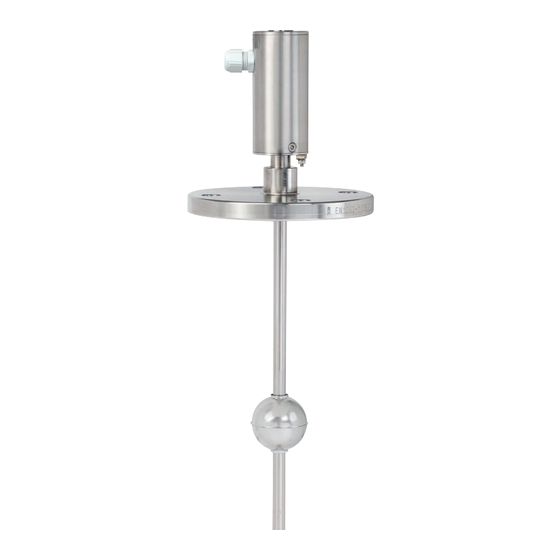
- Page 1 Operating instructions Betriebsanleitung Magnetostrictive level transmitter, models FLM-CA, FLM-CM Magnetostriktiv-Füllstandstransmitter, Typen FLM-CA, FLM-CM Mounting flange, spherical float from Mounting thread, cylinder float from stainless steel, model FLM-CA stainless steel, model FLM-CM...
- Page 2 Operating instructions models FLM-CA, FLM-CM Page 3 - 26 Betriebsanleitung Typen FLM-CA, FLM-CM Seite 27 - 50 © 09/2019 WIKA Alexander Wiegand SE & Co. KG All rights reserved. / Alle Rechte vorbehalten. WIKA is a registered trademark in various countries. ® WIKA ist eine geschützte Marke in verschiedenen Ländern.
-
Page 3: Table Of Contents
Contents Contents 1. General information 2. Design and function 3. Safety 4. Transport, packaging and storage 5. Commissioning, operation 6. Faults 7. Maintenance and cleaning 8. Dismounting, return and disposal 9. Specifications Operating instructions magnetostrictive level transmitter, models FLM-CA, FLM-CM... -
Page 4: General Information
2. Design and function 2.1 Description The models FLM-CA and FLM-CM high-accuracy level transmitters are used for the continuous measurement of the level of liquid media in vessels. The measurement procedure used exploits the physical effect of magnetostriction and is largely independent of the temperature. - Page 5 . The “BLM for bypass fitting” version is delivered without process connection and float. Operating instructions magnetostrictive level transmitter, models FLM-CA, FLM-CM...
- Page 6 From the time elapsed, the float position is determined. 2.3 Scope of delivery Cross-check scope of delivery with delivery note. Operating instructions magnetostrictive level transmitter, models FLM-CA, FLM-CM...
-
Page 7: Safety
Refrain from unauthorised modifications to the instrument. Any use beyond or different to the intended use is considered as improper use. Do not use this instrument in safety or emergency stop devices. Operating instructions magnetostrictive level transmitter, models FLM-CA, FLM-CM... - Page 8 Follow the instructions displayed in the work area regarding personal protective equipment! The requisite personal protective equipment must be provided by the operating company. Operating instructions magnetostrictive level transmitter, models FLM-CA, FLM-CM...
-
Page 9: Transport, Packaging And Storage
4.2 Packaging and storage Do not remove packaging until just before mounting. Keep the packaging as it will provide optimum protection during transport (e.g. change in installation site, sending for repair). Operating instructions magnetostrictive level transmitter, models FLM-CA, FLM-CM... -
Page 10: Commissioning, Operation
The level transmitter can also be installed in the vessel from below. If the vessel is also ■ pressurised, then the maximum length of the level transmitter is 2 m. Operating instructions magnetostrictive level transmitter, models FLM-CA, FLM-CM... - Page 11 5. Re-affix the adjusting collar , position and secure the threaded pins over the groove. 6. Position the process connection to its height and tighten the union nut finger-tight by hand. Operating instructions magnetostrictive level transmitter, models FLM-CA, FLM-CM...
- Page 12 To ensure a reliable measurement, the guide tube must be mounted free of tension, without external deformations. ▶ The distance between guide tube and bypass tube must be as slow as possible. ▶ Only floats approved by us can be used. Operating instructions magnetostrictive level transmitter, models FLM-CA, FLM-CM...
- Page 13 Guide tube, mounted free of tension (not deformed) Bypass tube Magnet position min. magnet position Bypass float Probe fixing (un-magnetic) Section A-A Spacer Operating instructions magnetostrictive level transmitter, models FLM-CA, FLM-CM...
- Page 14 Cable cross- Cable resistance per m voltage in V resistance in Ω section in mm² of copper cable in Ω/m 12 (-5 %) 0.0356 0.0178 0.0119 24 (-5 %) 0.0356 0.0178 0.0119 Operating instructions magnetostrictive level transmitter, models FLM-CA, FLM-CM...
- Page 15 = 86.8 Ω Cable resisatance R = 0.0356 Ω/m with cable cross-section Q = 0.5 mm² A cable with a forward and return line (2-wire) can therefore be a maximum of 1,000 m long. Operating instructions magnetostrictive level transmitter, models FLM-CA, FLM-CM...
- Page 16 6. Re-affix the screw terminal . The cable must not have any tension! 7. If required, set reference points (see chapter 5.3.1 “Measuring span on the level transmitter”). 8. Screw the probe head cover back down. Operating instructions magnetostrictive level transmitter, models FLM-CA, FLM-CM...
- Page 17 Pin 4 Pin 2 Pin 1 Pin assignment of the coupling of the WIKA connection cable Characteristic for connection cable between FLM-Cx and associated equipment: 2-wire, non-shielded cable The grounding or the equipotential bonding must be carried out by the installer in accordance with the applicable national installation regulations.
- Page 18 1. Unscrew the probe head cover using an open-ended spanner. 2. Hold down the 4 mA button or 20 mA button for a period of at least 3 seconds. The green LED starts to blink. Operating instructions magnetostrictive level transmitter, models FLM-CA, FLM-CM...
- Page 19 = 3.6 mA. Without pressing the button again, the level transmitter remains in Error error mode for another 2.5 seconds before it would switch back to measuring mode without changing the setting. Operating instructions magnetostrictive level transmitter, models FLM-CA, FLM-CM...
-
Page 20: Faults
If a return is needed, please follow the instructions given in chapter 8.2 “Return”. For contact details see chapter 1 “General information” or the back page of the operating instructions. The following table contains the most frequent causes of faults and the necessary countermeasures. Operating instructions magnetostrictive level transmitter, models FLM-CA, FLM-CM... -
Page 21: Maintenance And Cleaning
No work is allowed to be carried out unless by taking suitable personal protective measures (e.g. breathing apparatus, protective clothing etc.). ▶ Work on the instrument must only be carried out by trained skilled personnel. Operating instructions magnetostrictive level transmitter, models FLM-CA, FLM-CM... - Page 22 Do not use any aggressive cleaning agents. ▶ Do not use any hard or pointed objects for cleaning. 3. Wash or clean the dismounted instrument, in order to protect persons and the environment from exposure to residual media. Operating instructions magnetostrictive level transmitter, models FLM-CA, FLM-CM...
-
Page 23: Dismounting, Return And Disposal
8.3 Disposal Incorrect disposal can put the environment at risk. Dispose of instrument components and packaging materials in an environmentally compatible way and in accordance with the country-specific waste disposal regulations. Operating instructions magnetostrictive level transmitter, models FLM-CA, FLM-CM... -
Page 24: Specifications
Version with HART protocol Via two built-in buttons, HART communicator or HART ® ® ® interface in the connection housing For further specifications see data sheet LM 20.04 and the order documentation. Operating instructions magnetostrictive level transmitter, models FLM-CA, FLM-CM... - Page 25 Ingress protection per EN 60529 IP68 Configuration Via USB adapter with corresponding software and a standard computer Order number: 14361280 For further specifications see data sheet LM 20.05 and the order documentation. Operating instructions magnetostrictive level transmitter, models FLM-CA, FLM-CM...
- Page 26 The pressure strength can only be ensured for undamaged floats. Even the smallest and invisible dents, for example when the float falls from the table onto a stone floor, are sufficient to significantly reduce the pressure strength. Operating instructions magnetostrictive level transmitter, models FLM-CA, FLM-CM...
- Page 27 Inhalt Inhalt 1. Allgemeines 2. Aufbau und Funktion 3. Sicherheit 4. Transport, Verpackung und Lagerung 5. Inbetriebnahme, Betrieb 6. Störungen 7. Wartung und Reinigung 8. Demontage, Rücksendung und Entsorgung 9. Technische Daten Betriebsanleitung Magnetostriktiv-Füllstandstransmitter, Typen FLM-CA, FLM-CM...
-
Page 28: Allgemeines
LM 20.05 (FLM-CM) 2. Aufbau und Funktion 2.1 Beschreibung Die hochgenauen Füllstandstransmitter Typen FLM-CA und FLM-CM dienen zur konti- nuierlichen Füllstandsmessung von flüssigen Medien in Behältern. Das angewandte Messverfahren nutzt den physikalischen Effekt der Magnetostriktion aus und ist weitge- hend unabhängig von der Temperatur. Es findet besonders dort Anwendung, wo sehr exakte Füllstandsmessungen erforderlich sind, wie z. - Page 29 Schwimmer dient der kontinuierlichen Messung der Produktfüllhöhe oder Trennschicht und wird durch einen Stellring auf dem Gleitrohr gehalten. Die Ausführung „BLM zum Bypassanbau“ wird ohne Prozessanschluss und Schwimmer geliefert. Betriebsanleitung Magnetostriktiv-Füllstandstransmitter, Typen FLM-CA, FLM-CM...
- Page 30 Ende des Gleitrohres reflektiert. Die Zeit zwischen der Aussen- dung des Stromimpulses und dem Eintreffen der Welle am Sondenkopf wird gemessen. Aus den Laufzeiten wird die Schwimmerposition bestimmt. 2.3 Lieferumfang Lieferumfang mit dem Lieferschein abgleichen. Betriebsanleitung Magnetostriktiv-Füllstandstransmitter, Typen FLM-CA, FLM-CM...
-
Page 31: Sicherheit
Fehlgebrauch des Gerätes kann zu gefährlichen Situationen und Verletzungen führen. ▶ Eigenmächtige Umbauten am Gerät unterlassen. Jede über die bestimmungsgemäße Verwendung hinausgehende oder andersartige Benutzung gilt als Fehlgebrauch. Dieses Gerät nicht in Sicherheits- oder in Not-Aus-Einrichtungen benutzen. Betriebsanleitung Magnetostriktiv-Füllstandstransmitter, Typen FLM-CA, FLM-CM... - Page 32 Beim Ausführen der verschiedenen Arbeiten an und mit dem Gerät muss das Fachperso- nal persönliche Schutzausrüstung tragen. Im Arbeitsbereich angebrachte Hinweise zur persönlichen Schutzausrüstung befolgen! Die erforderliche persönliche Schutzausrüstung muss vom Betreiber zur Verfügung gestellt werden. Betriebsanleitung Magnetostriktiv-Füllstandstransmitter, Typen FLM-CA, FLM-CM...
-
Page 33: Transport, Verpackung Und Lagerung
Ser. No.: Art. No.: Tag. No.: 4 ... 20 mA max. DC 15 ... 30 V IP68 WIKA Alexander Wiegand SE & Co. KG Alexander-Wiegand-Strasse 30 63911 Klingenberg Level Sensor ??????? Typcode Type: ???-???????????????? 0637... -
Page 34: Inbetriebnahme, Betrieb
Messwertermittlung behindert werden kann. Der Füllstandstransmitter kann auch von unten in den Behälter eingebaut werden. Ist ■ der Behälter zusätzlich mit Druck beaufschlagt, dann beträgt die maximale Länge des Füllstandstransmitters 2 m. Betriebsanleitung Magnetostriktiv-Füllstandstransmitter, Typen FLM-CA, FLM-CM... - Page 35 Gleitrohr aufgeschoben werden, damit eine korrekte Messung erfolgen kann. 5. Stellring wieder aufstecken, Gewindestifte über der Nut positionieren und festziehen. 6. Prozessanschluss in seiner Höhe positionieren und Überwurfmutter mit der Hand fingerfest anziehen. Betriebsanleitung Magnetostriktiv-Füllstandstransmitter, Typen FLM-CA, FLM-CM...
- Page 36 Damit eine zuverlässige Messung gewährleistet ist, muss das Gleitrohr spannungsfrei ohne äußere Verformungen montiert werden. ▶ Der Abstand zwischen Gleit- und Bypassrohr muss möglichst gering sein. ▶ Es können nur von uns freigegebene Schwimmer verwendet werden. Betriebsanleitung Magnetostriktiv-Füllstandstransmitter, Typen FLM-CA, FLM-CM...
- Page 37 Montage mit Bypass BLM für Bypass Abstand Gleitrohr zu Schwimmermitte: max. Abstand abhängig vom Bypass- Schwimmer min. Magnet- position Gleitrohr span- nungsfrei montiert (unverformt) Bypassrohr Magnetposition min. Magnet- position Bypass-Schwimmer Sonderbefestigung (unmagnetisch) Schnitt A-A Abstandshalter Betriebsanleitung Magnetostriktiv-Füllstandstransmitter, Typen FLM-CA, FLM-CM...
- Page 38 Maximale Gesamtwiderstände bei unterschiedlichen Hilfsenergien sowie Kabelwiderstän- den bei verschiedenen Querschnitten: Hilfsenergie Max. Gesamt- Kabelquerschnitt Kabelwiderstand pro m in V widerstand in Ω in mm² Kupferkabel in Ω/m 12 (-5 %) 0,0356 0,0178 0,0119 24 (-5 %) 0,0356 0,0178 0,0119 Betriebsanleitung Magnetostriktiv-Füllstandstransmitter, Typen FLM-CA, FLM-CM...
- Page 39 Höchste Stromaufnahme I = 0,0215 A Bürde R = 86,8 Ω Kabelwiderstand R = 0,0356 Ω/m bei Kabelquerschnitt Q = 0,5 mm² Ein Kabel mit Hin- und Rückleitung (2-adrig) kann also maximal 1.000 m lang sein. Betriebsanleitung Magnetostriktiv-Füllstandstransmitter, Typen FLM-CA, FLM-CM...
- Page 40 5. 2-adriges Kabel an die mit (+) und (–) gekennzeichneten Pole an der Schraubklem- me anschließen. 6. Schraubklemme wieder aufstecken. Das Kabel darf keine Zugkraft haben! 7. Falls erforderlich, Referenzpunkte einstellen (siehe Kapitel 5.3.1 „Messbereichsspanne am Füllstandstransmitter“). 8. Sondenkopfdeckel wieder aufschrauben. Betriebsanleitung Magnetostriktiv-Füllstandstransmitter, Typen FLM-CA, FLM-CM...
- Page 41 2-adriges, nicht abgeschirmtes Kabel Die Erdung bzw. den Potentialausgleich durch den Errichter gemäß der jeweils national gültigen Errichtungsvorschrift vornehmen. Der Erdungsanschluss des Sondenkopfes kann für die Erdung bzw. den Potentialausgleich verwendet werden. Bitte auch die allgemeinen Errichtungsvorschriften beachten. Betriebsanleitung Magnetostriktiv-Füllstandstransmitter, Typen FLM-CA, FLM-CM...
- Page 42 1. Sondenkopfdeckel mit Hilfe eines Gabelschlüssels abschrauben. 2. 4 mA-Taste oder 20 mA-Taste für einen Zeitraum von mindestens 3 Sekunden gedrückt halten. Die grüne LED beginnt zu blinken. Betriebsanleitung Magnetostriktiv-Füllstandstransmitter, Typen FLM-CA, FLM-CM...
- Page 43 = 21,5 mA, erlischt die LED, so beträgt I = 3,6 mA. Ohne erneuten Fehler Fehler Tastendruck bleibt der Füllstandstransmitter für weitere 2,5 Sekunden im Fehlermodus bevor er ohne Ändern der Einstellung zurück in den Messmodus wechseln würde. Betriebsanleitung Magnetostriktiv-Füllstandstransmitter, Typen FLM-CA, FLM-CM...
-
Page 44: Störungen
▶ Bei notwendiger Rücksendung die Hinweise unter Kapitel 8.2 „Rücksen- dung“ beachten. Kontaktdaten siehe Kapitel 1 „Allgemeines“ oder Rückseite der Betriebsanlei- tung. In der folgenden Tabelle sind die häufigsten Fehlerursachen und erforderliche Gegenmaß- nahmen aufgeführt. Betriebsanleitung Magnetostriktiv-Füllstandstransmitter, Typen FLM-CA, FLM-CM... -
Page 45: Wartung Und Reinigung
Beim Arbeiten an Behältern besteht Vergiftungs- oder Erstickungsgefahr. ▶ Arbeiten dürfen nur unter Anwendung geeigneter Personenschutzmaßnah- men (z. B. Atemschutzgerät, Schutzkleidung o. Ä.) durchgeführt werden. ▶ Arbeiten am Gerät dürfen nur durch geschultes Fachpersonal erfolgen. Betriebsanleitung Magnetostriktiv-Füllstandstransmitter, Typen FLM-CA, FLM-CM... - Page 46 Eine unsachgemäße Reinigung führt zur Beschädigung des Gerätes! ▶ Keine aggressiven Reinigungmittel verwenden. ▶ Keine harten und spitzen Gegenstände zur Reinigung verwenden. 3. Ausgebautes Gerät spülen bzw. säubern, um Personen und Umwelt vor Gefährdung durch anhaftende Messstoffreste zu schützen. Betriebsanleitung Magnetostriktiv-Füllstandstransmitter, Typen FLM-CA, FLM-CM...
-
Page 47: Demontage, Rücksendung Und Entsorgung
Hinweise zur Rücksendung befinden sich in der Rubrik „Service“ auf unserer lokalen Internetseite. 8.3 Entsorgung Durch falsche Entsorgung können Gefahren für die Umwelt entstehen. Gerätekomponenten und Verpackungsmaterialien entsprechend den landesspezifischen Abfallbehandlungs- und Entsorgungsvorschriften umweltgerecht entsorgen. Betriebsanleitung Magnetostriktiv-Füllstandstransmitter, Typen FLM-CA, FLM-CM... -
Page 48: Technische Daten
-Protokoll Über zwei eingebaute Tasten im Anschlussgehäuse ® Version mit HART -Protokoll Über zwei eingebaute Tasten, HART -Kommunikator ® ® oder HART -Schnittstelle im Anschlussgehäuse ® Weitere technische Daten siehe Datenblatt LM 20.04 und Bestellunterlagen. Betriebsanleitung Magnetostriktiv-Füllstandstransmitter, Typen FLM-CA, FLM-CM... - Page 49 Abhängig vom Schwimmer, max. 40 bar Betriebstemperatur -40 ... +125 °C Umgebungstemperatur -40 ... +85 °C Schutzart nach EN 60529 IP68 Konfiguration Über USB-Adapter mit entsprechender Software und Standard-Computer Bestellnummer: 14361280 Weitere technische Daten siehe Datenblatt LM 20.05 und Bestellunterlagen. Betriebsanleitung Magnetostriktiv-Füllstandstransmitter, Typen FLM-CA, FLM-CM...
- Page 50 Die Druckfestigkeit kann nur für unbeschädigte Schwimmer gewährleistet werden. Selbst kleinste und nicht sichtbare Dellen, die z. B. entstehen, wenn der Schwimmer vom Tisch auf einen Steinboden fällt, genügen, um die Druck- festigkeit deutlich herabzusetzen. Betriebsanleitung Magnetostriktiv-Füllstandstransmitter, Typen FLM-CA, FLM-CM...
- Page 51 Operating instructions magnetostrictive level transmitter, models FLM-CA, FLM-CM...
- Page 52 KSR Kuebler subsidiaries worldwide can be found online at www.ksr-kuebler.com. WIKA subsidiaries worldwide can be found online at www.wika.com. Manufacturer contact: Sales contact: A division of the WIKA group KSR Kuebler Niveau-Messtechnik GmbH WIKA Alexander Wiegand SE & Co. KG...
Need help?
Do you have a question about the FLM-CA and is the answer not in the manual?
Questions and answers