
Related Manuals for Lutron Electronics YK-2005LX


Summary of Contents for Lutron Electronics YK-2005LX
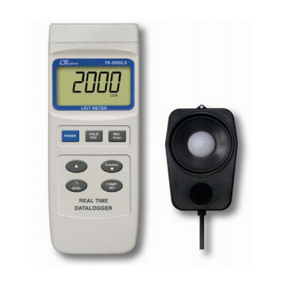
- Page 1 200/2,000/20,000/100,000 Lux, LUX/Feet-candle Real time data logger, 16000 Data logger no., RS232 LIGHT METER Model : YK-2005LX...
-
Page 2: Table Of Contents
TABLE OF CONTENTS 1. FEATURES..............1 2. SPECIFICATIONS............2 2-1 General Specifications.......... 2 2-2 Electrical Specifications........4 3. FRONT PANEL DESCRIPTION........5 4. GENERAL MEASURING PROCEDURE......7 4-1 Light measurement..........7 4-2 Data Hold............9 4-3 Data Record (Max., Min. reading)......9 4-4 Data Logger............10 5. -
Page 3: Features
1. FEATURES * Wide range, 200/2,000/20,000/100,000 LUX. * LUX & Foot Candle unit selection. * Spectrum of photo sensor meets C.I.E.. * 4 kinds selection lighting type (Tungsten, Fluorescent, Sodium or Mercury light ). * Zero adjustment by push button. * Auto range or manual range can be defaulted. -
Page 4: Specifications
2. SPECIFICATIONS 2-1 General Specifications Circuit Custom one-chip of microprocessor LSI circuit. Display LCD size : 58 mm x 34 mm. Measurement LUX, Feet candle ( Ft-cd ) Unit Lighting Type Normal ( Tungsten ) light Selection Fluorescent light Sodium light Mercury light Light The exclusive photo diode &... - Page 5 Sampling Time Approx. 1 second. of display Data Output RS 232 PC serial interface. Operating 0 to 50 ℃ Temperature Operating Less than 80% R.H. Humidity Power Supply DC 1,5 V battery ( UM3 ) x 4 PCs, ( Heavy duty type ). * main instrument DC 9V adapter input.
-
Page 6: Electrical Specifications
2-2 Electrical Specifications (23± 5 ℃ Measuremen Range Max. In-range Display 200 LUX 0 - 199.9 LUX 2,000 LUX 180 - 1,999 LUX 20,000 LUX 1,800 - 19,990 LUX 100,000 LUX 18,000 - 100,000 LUX Ft-cd 0 - 18.6 Ft-cd Ft-cd 16.7 - 186.0 Ft-cd Feet-candle... -
Page 7: Front Panel Description
3. FRONT PANEL DESCRIPTION... - Page 8 3-1 Display 3-2 Power Button 3-3 HOLD Button ( ESC Button ) 3-4 REC Button ( Enter Button ) 3-5 SOURCE/ZERO ( Up Button ▲ 3-6 Range Button ( Down Button ) ▼ 3-7 Send Button ( Clock Button ) 3-8 SET Button ( Logger Button ) 3-9 Stand 3-10 Battery Compartment/Cover...
-
Page 9: General Measuring Procedure
4. GENERAL MEASURING PROCEDURE The meter default function are following : * The display unit is LUX. * Auto range. * Auto power off. * The light type is Normal ( Tungsten ). * The sampling time of data logger function is 2 seconds. - Page 10 Measurement Consideration 1)Light type selection The light meter is calibrated under a precision " Standard light tungsten incandescent source of 2856 K degree ". Meter light type is selected is to " Normal ( Tungsten. ) " . The meter default light type is Normal " Tung. " type.
-
Page 11: Data Hold
2)If intend to change the display unit from LUX to Ft-cd ( feet candle ), please refer page 15, chapter 5-6 ( Unit Default Setting ) 3)The meter is defaulted to auto range function. However if intend to use the meter under manual range, please refer page 15, chapter 5-7 ( Auto/Manual Default Setting ) For the manual range operation, press the "... -
Page 12: Data Logger
* With the " REC. " symbol on the display : a) Press the " REC Button " ( 3-4, Fig. 1 ) once, the " REC. MAX. " symbol along with the maximum value will appear on the display. If intend to delete the maximum value, just press the "... - Page 13 c) Auto Data Logger ( Sampling time set from 2 seconds to 8 hours 59 minutes 59 seconds ) Press the " Logger Button " ( 3-8, Fig. 1 ) once to start the Auto Data Logger function, at the same the bottom right display will show the indicator "...
-
Page 14: Advanced Adjustment Procedure
Remark : If intend to change the data logger sampling time, please refer chapter 5-4. If intend to know the space of balance data numbers into the memory IC, please refer chapter 5-1. If intend to clear the saving data from the memory please refer chapter 5-2. -
Page 15: Check Memory Space
b. One by one to press the " Set Button " ( 3-8, Fig. 1 ) once a while to select the ten main function, at the same time lower display will show on the lower display will show on the lower display as : Memory Space Clear Memory Date/Time Set... -
Page 16: Clear Memory
5-2 Clear Memory * To delete the existing save data numbers from the memory. * Push ENTER Button once, then push ENTER Button to confirm. * Press the ESC Button once to quite and return to the main measurement manual. 5-3 Date/Time Setting * Use Up Button,... -
Page 17: Unit Default Setting
* After finish the Auto Power Off adjustment, push the " Enter Button " , then press the " ESC Button " will quite and return to the normal measurement display. 5-6 Unit Default Setting * Use Up Button, Down Button to select the ▲... -
Page 18: How To Send The Data Out From The Meter
6. HOW TO SEND THE DATA OUT FROM THE METER 1)If intend to send the data out from the meter, it should cancel the " Hold function " and the " Record function " first. The display will not show the " HOLD " and the "... - Page 19 The meter can save 16,000 data max. , those data will saved into 250 memory block max. * The data that save into one routine Data Logger procedures ( Push " REC " button , following push the " Logger " button to save the data, the display will show the "...
- Page 20 3)Until the desired Memory Block no. be selected. Push the " Send Button " ( 3-7, Fig. 1 ) once, the data in the Memory Block will send out. During the data send out, the bottom right display will show the " Sending Data ! " indicator. When data already send out completely, the bottom right display will show the Transmit mode "...
-
Page 21: Rs232 Pc Serial Interface
7. RS232 PC SERIAL INTERFACE The instrument has RS232 PC serial interface via a 3.5 mm terminal ( 3-14, Fig. 1 ). The data output is a 16 digit stream which can be utilized for user's specific application. A RS232 lead with the following connection will be required to link the instrument with the PC serial port. - Page 22 Each digit indicates the following status : End Word = 0D D1 & D8 Display reading, D1 = LSD, D8 = MSD For example : If the display reading is 1234, then D8 to D1 is : 00001234 Decimal Point(DP), position from right to the left 0 = No DP, 1= 1 DP, 2 = 2 DP, 3 = 3 DP Polarity...
-
Page 23: Battery Replacement
8. BATTERY REPLACEMENT 1)When the left corner of LCD display show " ", it is necessary to replace the batteries ( UM3/1.5 V x 4 PCs ). 2)Slide the " Battery Cover " ( 3-7, Fig. 1 ) away from the instrument and remove the battery. -
Page 24: Optional Accessories
During the Power On, used a pin tool to push the " System Reset Switch " ( 3-13, Fig. 1 ) once 10. OPTIONAL ACCESSORIES RS232 cable * Isolated RS232 cable. UPCB-02 * Used to connect the meter to the computer Data Logger * Software the used to download software... -
Page 25: Spectrum Of Light Sensor
11. SPECTRUM of LIGHT SENSOR 0612-YK2005LX...
Need help?
Do you have a question about the YK-2005LX and is the answer not in the manual?
Questions and answers