Advertisement
DESCRIPTION
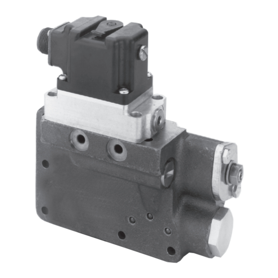
The MCV104A Electrical Displacement Control (EDC) is a
two-stage electrohydraulic pump stroke control which uses
a mechanical feedback to establish closed-loop control of the
swashplate angle of Sauer-Danfoss Series 2X and 3X pumps.
pressure proportional to the applied electrical signal. The
second stage uses the
spool arrangement and port oil to the pump servocylinders. The
sec
machine safety) in the pump's output while maintaining
optimum dynamic response to control commands.
FEATURES
•
Single command source can be used to control both
hydrostatic pump and motor.
•
Servo control deadband independent of signal null dead-
band: offers safety combined with accurate and responsive
control.
•
interface, full environmental testing.
•
Minimum long term null shift.
•
Pilot supply screens in series, upstream screen is externally
serviceable.
ORDERING INFORM ATION
A range of options to the basic EDC allows it to be custom-tai-
each slot of the two order numbers, as shown in Tables A and
B. Consult Sauer-Danfoss, Minneapolis, MN, with further ques-
tions.
Previous to September, 1985, Electrical Displacement Controls
(EDC's) and Hydraulic Displacement Controls (HDC's) were sold
with appropriate linkage assemblies installed for the various
pump options. In order to simplify the inventory process, and
thereby provide faster delivery to customers, this single ordering
number, as described further in the scheme outlined in Table A,
remains the same - the only change being that a "9" is always
valve without linkage, allows the EDC or HDC to be mounted on
any pump or motor. The second number to be included with the
is to be mounted. This in turn determines the components of
the mounting kit, including the appropriate link.
© Danfoss, 2013
erential pressure to drive its double
K07116 • Rev AB • September 2013
MCV104A
Electrical Displacement Control
K07116
-
•
stroke.
•
First and second stages can be individually replaced.
•
Swashplate movement can be visually detected.
•
Single or dual coil torque motor.
•
4 to 20 mA control option.
•
Intrinsically safe control option for hazardous atmosperic
environments.
TABLE A. INFORMATION NECESSARY TO SPECIFY
THE EDC
DEVICE IDENTITY
CONFIGURATION
SERIES*
PILOT STYLE
*
in the series slot for the control's order number; A "9" indicates
a generic control.
Issued: November 2003
MCV104A X 9 XX
1
Advertisement
Table of Contents

Related Manuals for Danfoss MCV104A


Summary of Contents for Danfoss MCV104A
- Page 1 Electrical Displacement Control K07116 Issued: November 2003 DESCRIPTION The MCV104A Electrical Displacement Control (EDC) is a two-stage electrohydraulic pump stroke control which uses a mechanical feedback to establish closed-loop control of the swashplate angle of Sauer-Danfoss Series 2X and 3X pumps.
- Page 2 ORDERING INFORMATION (continued) DEVICE IDENTITY This is the basic EDC. The model code is MCV104A. from condensing on the inside during extreme temperature changes. Dual coil valves have all four pin connections active. CONFIGURATION See the Wiring section. MODEL PRESSURE...
-
Page 3: Spare Parts
For items 17, 18, 20, 21, 22, 25 and 36-42 it is recommended to purchase the appropriate installation kit ensuring the necessary items for a complete EDC installation. Item 30 is used for the 14-85 mA models. Item 31 is used for the 4-20 mA models. K07116 • Rev AB • September 2013 © Danfoss, 2013... -
Page 4: Service Parts
Note: The Deutsch electrical connectors are not shown. See Item 4, a change was made in January 2000 that increased the null See Item 5, the preferred part number K28475 includes the cover, gaskets, null access screw, and all the cover seals. K07116 • Rev AB • September 2013 © Danfoss, 2013... -
Page 5: Technical Data
EDC’s. 18∞ 1141 COIL RESISTANCE @ 24° C (76° F) Current Vs. Swashplate Angle for the MCV104A. 23 ohms (single coil) Single-Coil Load Pressure is 3000 PSI and Current Input is 0.01 19.5 ohms (A, B Terminals), 15.5 ohms (C, D Terminals) (dual coil) - Page 6 Packard or MS Connector; or pins 2 or 4 of the Duetsch Connector) produces a pressure rise at Output Port-C2. 1122G Dimensions of the MCV104A in Millimeters [Inches]. Table of Mounting Bolt Dimensions, Quantity and Part Number by Pump Series. SERIES DIM "C"...
-
Page 7: Theory Of Operation
12 psi, which is the amount of INTERNAL WORKINGS SCHEMATIC, WITH OPTIONAL PRESSURE OVERRIDE 1302 Schematic of the Internal Workings of the MCV104A with Optional Pressure Override Valve. Oil Paths Shown Externally for Clarity. K07116 • Rev AB • September 2013... - Page 8 INTERNAL WORKINGS SCHEMATIC, WITHOUT OPTIONAL PRESSURE 1303 Schematic of the Internal Workings of the MCV104A Without Optional Pressure Override Valve. Oil Paths Shown Externally For Clarity. TIME VS. SWASHPLATE ANGLE High response Non-high response ED C Time (second) Time (second) 1301 Time vs.
- Page 9 Crimp in the locations shown in Distance, Packard Connector diagram with a Packard 12014254 crimp tool See Ordering Information. available from your local Packard distributor. K07116 • Rev AB • September 2013 © Danfoss, 2013...
- Page 10 Distance From Tang to Third Rib of Packard Connector. CONNEC TOR PARTS IDENTIFIE D, PACKARD CONNEC TOR SIDE "B" CABLE SEALS SIDE "A" SHROUD CONNECTOR DOUBLE-PLUG SEAL TOWER CONNECTOR 1078A K07116 • Rev AB • September 2013 © Danfoss, 2013...
-
Page 11: Troubleshooting Steps
3/32 inch kex key, replace screw 3002 CAUTION control (EDC), pump or motor, do not adjust the pilot null. Adjust the second stage valve null. K07116 • Rev AB • September 2013 © Danfoss, 2013... -
Page 12: Installation
See Swashplate Location diagram. 1124B Swashplate Drag Link/Control Feedback Link Connection Between Original Control and Pump. K07116 • Rev AB • September 2013 © Danfoss, 2013... -
Page 13: Pin Connection
Engage the pin on the control in the drag link and swing the control into place against the pump housing. The drag n i l . e t Install the seven mounting screws and tighten to 10-11 foot pounds of torque. K07116 • Rev AB • September 2013 © Danfoss, 2013... -
Page 14: Pump Neutral Adjustment
(charge pressure will rise approxi- GAUGE PORT mately 20 psi in neutral and drop when going into stroke due to the shifting of the shuttle valve in the motor manifold). 1143A K07116 • Rev AB • September 2013 © Danfoss, 2013... - Page 15 8 9 2 6 Single Coil MS MCV104A 4 or 8 0 thru 9 5 or 6 MCV104A 8 9 2 7 Dual Coil MS MCV104A 4 or 8 0 thru 9 7 or 8 K07116 • Rev AB • September 2013 © Danfoss, 2013...
- Page 16 MCV104A4927 Pressure Override & Servo Ports & High Response D062-512D,E, OR F MCV104A1927 Servo Ports E062-562 MCV104A5927 D062-862D MCV104A5927 63-500 MCV104A5927 Note, the Moog 62-xxxx and 63-xxxx are the same. K07116 • Rev AB • September 2013 © Danfoss, 2013...
Need help?
Do you have a question about the MCV104A and is the answer not in the manual?
Questions and answers