Advertisement
Quick Links
SIXTY0
DIRECT VENT LOG SET KIT
PART #: LGS-60
INSTALLATION MANUAL
ONLY FOR USE ON SÓLAS MODELS: 60N-SSL, 60P-SSR, 60N-ST, 60P-SSL, 60P-SSR, 60P-ST
WARNING
This log set kit shall be installed by a qualified service agency in accordance with
the manufacturer's instructions and all applicable codes and requirements of the
Authority Having Jurisdiction. If the information in these instructions is not
followed exactly, a fire, explosion or production of carbon monoxide may result
causing property damage, personal injury or loss of life. The qualified service
agency is responsible for the proper installation of this kit. The installation is not
proper and complete until the operation of the converted appliance is checked as
specified in the manufacturer's instructions supplied with the kit.
NOT FOR USE WITH VENT FREE OR OUTDOOR FIREPLACES
0
Advertisement

Related Manuals for Solas SIXTY0 LGS-60


Summary of Contents for Solas SIXTY0 LGS-60
- Page 1 SIXTY0 DIRECT VENT LOG SET KIT PART #: LGS-60 INSTALLATION MANUAL ONLY FOR USE ON SÓLAS MODELS: 60N-SSL, 60P-SSR, 60N-ST, 60P-SSL, 60P-SSR, 60P-ST WARNING This log set kit shall be installed by a qualified service agency in accordance with the manufacturer’s instructions and all applicable codes and requirements of the Authority Having Jurisdiction.
- Page 2 LOG SET INSTALLATION Kit Contents: • (5) Ceramic Logs • 1lb 11oz Lava Rock • (6) Ceramic Rocks • Metal Logset burner set Figure 01 - Burner Support locations Step #1 Your fireplace will have shipped from the factory with the Glass Media burners in place, before installing the logset burners, we need to remove the glass burners.
- Page 3 LOG SET INSTALLATION Step #3 To remove the right burner, remove the 4 sheet metal screws securing the right burner, these screws are identified by the 4 arrows below. Once all hardware has been removed, slide the burner to the right and lift the burner out of the fireplace. Remove the burner by sliding the assembly to the right, then lifting up into the room.
- Page 4 LOG SET INSTALLATION Step #6 Install the left logset burner within the firebox by lowering the burner into the firebox. (while keeping the burner pressed toward the left side of the firebox) then sliding the burner right towards the center of the firebox to engage the burner orifice. Confirm that the burner inlet tube has engaged the burner orifice.
- Page 5 LOG SET INSTALLATION Step #7 Install the right logset burner within the firebox by lowering the burner into the firebox. (while keeping the burner pressed toward the right side of the firebox) then sliding the burner left towards the center of the firebox to engage the burner orifice. Confirm that the burner inlet tube has engaged the burner orifice.
- Page 6 LOG SET INSTALLATION Step #8 Secure the central burner link using the (2) sheet metal screws from step #2. Figure 12 shows the burners before the burner link is installed; Figure 13 shows the burners after the burner link has been installed. Figure 12 Figure 13 Step #9...
- Page 7 LOG SET INSTALLATION Step #11 Install the single rock as shown in figure 16 on the 2 pins projecting up from the rear edge of the burner top, left of the center log installed in Step #10. Figure 16 Figure 17 Step #12 Install the pair of single rocks as shown in figure 17 on the 2 sets of pins projecting up from the left side of the left burner as shown in figure 17 above.
-
Page 8: Log Set Installation
LOG SET INSTALLATION Step #14 At the midpoint of the left burner, centered between the rock and log features installed during steps 9-13, are 2 pins to locate the rock shown in Figure 19. Note the orientation of the tab on the top surface of the rock (identified by the arrow in Figure 19). - Page 9 LOG SET INSTALLATION Step #16 The 3-rock cluster installed in Step 15 supports the left side of the large log shown in Figure 22. The right side of the log rests on the burner, a groove in the underside of the log interfaces with the front edge of the burner, slide the log to the right until the tip of the log is about to contact the enamel side panel.
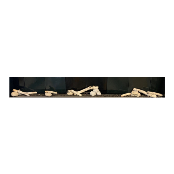
- Page 10 LOG SET INSTALLATION Installation is now complete, refer to the SIXTY0 Owner’s manual for instructions on final assembly and lighting of the appliance.
Need help?
Do you have a question about the SIXTY0 LGS-60 and is the answer not in the manual?
Questions and answers