Table of Contents
Advertisement
Quick Links
Advertisement
Table of Contents

Subscribe to Our Youtube Channel
Related Manuals for Woods TURF BATWING TBW150C


Summary of Contents for Woods TURF BATWING TBW150C
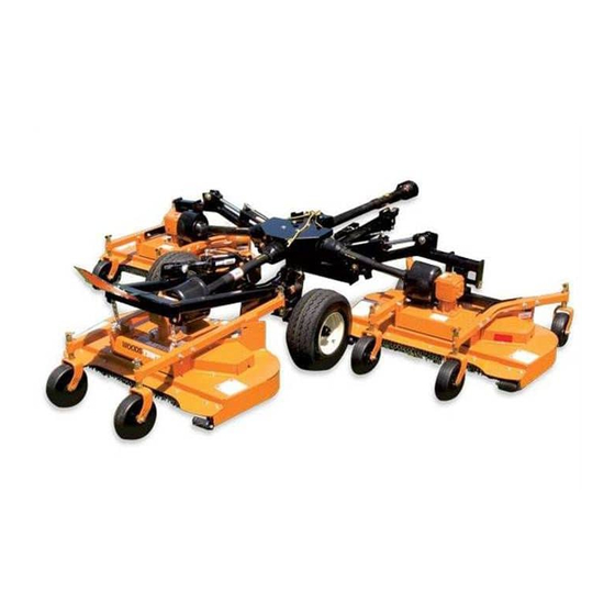
- Page 1 TURF BATWING ® TBW150C...
-
Page 2: Introduction
TO THE OWNER: Read this manual before operating your Woods equipment. The information presented will prepare you to do a better and safer job. Keep this manual handy for ready reference. Require all operators to read this manual carefully and become acquainted with all adjustment and operating procedures before attempting to operate. -
Page 3: Table Of Contents
TABLE OF CONTENTS INTRODUCTION ..............2 SPECIFICATIONS . -
Page 4: Specifications
SPECIFICATIONS Cutting Width 12.5’ Cutting Height Range 1.0” - 4.5” Shipping Weight (Approximately) 2,035 lbs. Blade Speed (feet per minute) 16,200 Blade Spindles Number of Blades Universal Drive Series (Input: ASAE Cat 3 CV; Wing: ASAE Cat 3) Transport Wheels 20.5”... -
Page 5: Safety 5
SAFETY RULES ATTENTION! BECOME ALERT! YOUR SAFETY IS INVOLVED! Never allow children or untrained persons to Safety is a primary concern in the design and operate equipment. manufacture of our products. Unfortunately, our efforts to provide safe equipment can be wiped PREPARATION out by an operator’s single careless act. -
Page 6: Transportation
SAFETY RULES ATTENTION! BECOME ALERT! YOUR SAFETY IS INVOLVED! Power unit must be equipped with ROPS or machines. This speed is the ground speed limita- tion. ROPS cab and seat belt. Keep seat belt securely EXAMPLE: If the tractor is capable of 40 km/h, fastened. -
Page 7: Maintenance
SAFETY RULES ATTENTION! BECOME ALERT! YOUR SAFETY IS INVOLVED! stopped when anyone comes within 300 feet (92 Power unit must be equipped with ROPS or ROPS cab and seat belt. Keep seat belt securely • This shielding is designed to reduce the risk of fastened. -
Page 8: Storage
SAFETY RULES ATTENTION! BECOME ALERT! YOUR SAFETY IS INVOLVED! Before performing any service or maintenance, Tighten all bolts, nuts, and screws to torque lower equipment to ground or block securely, turn chart specifications. Check that all cotter pins are off engine, remove key, and disconnect driveline installed securely to ensure equipment is in a safe from tractor PTO. -
Page 9: Safety & Instructional Decals
Replacement safety decals can be ordered free from your Woods dealer. To locate your nearest dealer, check the Dealer Locator at www.WoodsEquipment.com, or in the United States and Canada call 1-800-319-6637. - Page 10 SAFETY & INSTRUCTIONAL DECALS ATTENTION! BECOME ALERT! YOUR SAFETY IS INVOLVED! Replace Immediately If Damaged! 6 -18867 8 - 1004114 5 - 18865 7 - 1003751 9 - 1029508 10 Safety MAN0765 (12/5/2008)
- Page 11 SAFETY & INSTRUCTIONAL DECALS ATTENTION! BECOME ALERT! YOUR SAFETY IS INVOLVED! Replace Immediately If Damaged! 11 - 18866 17 - Serial Number Plate 12 - 18869 18 - 611520 14 - 44656 19 - 611521 - SIS 30 KM/H Safety 11 Rev.
- Page 12 SAFETY & INSTRUCTIONAL DECALS ATTENTION! BECOME ALERT! YOUR SAFETY IS INVOLVED! Replace Immediately If Damaged! 10 - 33347 13 - 18877 15 - 1002941 16 - W19924 12 Safety (Rev. 6/04/2018) MAN0765 (12/5/2008)
-
Page 13: Operation 13
OPERATION The operator is responsible for the safe operation of Make sure spring-activated locking pin or collar the mower. The operator must be properly trained. slides freely and is seated firmly in tractor PTO Operators should be familiar with the mower, the trac- spline groove. -
Page 14: Cutting Height Adjustment
3. Attach the safety chain to the tractor as shown in Check for excessive turn angle: Figure 1. 1. Disconnect the driveline from the tractor. 4. Attach the mower drive shaft to tractor PTO. Make 2. Start engine and turn as far right or left as possible. sure the lock collar engages securely. -
Page 15: Transport
STARTING AND STOPPING MOWER blades to contact ground repeatedly will cause damage to mower and drive. ARNING 1. Level mower from side to side. Check by measuring from mower frame to the ground at Do not operate PTO during transport. each deck rail. -
Page 16: Removing Mower From Tractor
PTO speed to 540 RPM and maintain speed through- Extremely tall material should be cut twice. Set mower out the cutting operation. at a higher cutting height for the first pass. Then cut at desired height 90 degrees to the first pass. Mower vibration tends to loosen bolts. -
Page 17: Pre-Operation Checklist
PRE-OPERATION CHECK LIST on driveline. Fasten tether chains as instructed to the tractor and the equipment. (OWNER's RESPONSIBILITY) ___ Review and follow all safety rules and safety ___ Inspect area and remove stones, branches or decal instructions on page 5 through page 12. other hard objects that might be thrown, causing injury or damage. -
Page 18: 18 Owner Service
OWNER SERVICE The information in this section is written for operators who possess basic mechanical skills. If you need help, CAUTION your dealer has trained service technicians available. sure, set parking brake, stop engine, remove key, For your protection, read and follow the safety informa- and unfasten seat belt. - Page 19 Seasonal Lubrication 3. Place joints in the straight position and add 10 additional pumps of grease to both joints. In addition to the daily recommended lubrication, a more extensive application is recommended season- 4. Wipe telescoping drive clean of all old grease and ally.
- Page 20 DESCRIPTION FREQUENCY Driveline U-Joints 8 Hours Telescoping Shaft 8 Hours Shield Bearing 8 Hours Gearbox (Fill 1/2 Check full w/SAE 90W gear lube Daily Caster Wheel Hubs 8 Hours Caster Pivots 8 Hours Blade Spindles 40 Hours Wing Pivot 8 Hours Deck Pivot 8 Hours Figure 3.
-
Page 21: Belt Servicing
BELT SERVICING idler with belt to obtain enough belt length to route it over pulley E. Make sure spring-loaded idler Belt Replacement pivots freely with belt installed. One of the major causes of belt failure is improper BLADE SERVICING installation. Before installing a new belt, check the fol- ARNING lowing: 1. -
Page 22: Chain Shielding
Figure 5. Blade Balancing 1. Follow original sharpening pattern. 2. Do not sharpen blade to a razor edge, but leave Figure 7. Blade and Spindle Assembly approximately 1/64" blunt edge. 1. Place blade over blade pilot on the bottom of the 3. -
Page 23: Cleaning
Sand down scratches and the edges of areas of ● Periodically or Before Extended Storage missing paint and coat with Woods spray paint of matching color (purchase from your Woods Clean large debris such as clumps of dirt, grass, dealer). - Page 24 TROUBLESHOOTING BELT CONDITIONS PROBLEM POSSIBLE CAUSE SOLUTION Belt slippage Mower overloading; material too Reduce tractor ground speed but tall or heavy maintain full PTO rpm. Cut material twice, one high pass and then mow at desired height. Cut 90 degrees to first pass. Oil on belt from over-lubrication Be careful not to over-lubricate.
-
Page 25: Dealer Service 25
DEALER SERVICE The information in this section is written for dealer ser- 2. Remove sheave (3) and spacer (4). vice personnel. The repair described here requires NOTE: A wheel puller may be needed if sheave special skills and tools. If your shop is not properly can not be removed by hand. -
Page 26: Gearbox Repair
3. Insert shaft assembly with bearing and spacer into seal but will clear the housing. Tubing with an OD spindle housing from the bottom. that is too small will bow seal cage and ruin seal. 4. Install upper bearing (5) over shaft with the seal 5. - Page 27 Disassemble Gearbox 3. If the leak occurred at either end of horizontal shaft, remove oil cap (11) and/or oil seal (1). Replace Refer to Figure 11. with new one (see Seal Replacement, page 26). 1. Remove top cover (28) from housing. Turn gearbox 4.
- Page 28 4. Press output shaft assembly into housing from the 13. Slide shim (3) over input shaft and secure with bottom opening. snap ring (2). 5. Install snap ring (18) in bottom of housing. 14. Check input shaft end float by moving the input shaft by hand.
-
Page 29: Universal Joint Repair
Install Gearbox UNIVERSAL JOINT REPAIR NOTE: Gearbox is heavy: do not attempt to move with- 1. Yoke out mechanical assistance. 2. Cup and bearings 1. Set gearbox on gearbox stand and fasten with 3. Snap ring bolts and nuts. Torque bolts to 175 lbs-ft. 4. - Page 30 3. Clamp cup in vise as shown in 4. and tap on yoke shaft. Be careful not to disturb needle bearings. to completely remove cup from yoke. Repeat Step Insert another bearing cup directly across from first 2 & Step 3 for opposite cup. cup and press in as far as possible with hand pressure.
-
Page 31: Assembly 31
5. Attach parking jack to trailer tongue frame. The mower is shipped mostly assembled but requires 6. Remove wood block from hitch. dealer set-up. The Woods dealer should deliver the mower to the owner completely assembled, lubricated, Attach Hydraulic Hoses and adjusted for normal conditions. - Page 32 1. Install chain shielding plate (3) to rear mower frame 1. Remove rope lever from the top of front latch. as shown. 2. Remove plugs from front and rear ports on cylinder 2. Secure with carriage bolts (14) and flanged lock and extend cylinder rod.
- Page 33 Mulch Kit Installation NOTE: Do not tighten hardware until mulch kit is com- pletely installed. 1. Raise deck and lock into transport position. NOTE: Make sure deck is stable before proceed- ing. 2. Remove chain shielding installed. Chain shielding is not required when using mulch kit. 3.
-
Page 34: Dealer Check Lists
DEALER CHECK LISTS PRE-DELIVERY CHECK LIST DELIVERY CHECK (DEALER’S RESPONSIBILITY) (DEALER’S RESPONSIBILITY) Inspect the equipment thoroughly after assembly to ___ Show customer how to make adjustments and ensure it is set up properly before delivering it to the select proper PTO speed. customer. -
Page 35: Parts Index
PARTS INDEX Turf Batwing Mower TBW 150C MAIN FRAME ASSEMBLY ......36 & 37 DECK ASSEMBLY . - Page 36 MAIN FRAME ASSEMBLY 36 Parts Rev. 6/15/2021) MAN0765 (12/5/2008)
- Page 37 MAIN FRAME ASSEMBLY PARTS LIST PART DESCRIPTION PART DESCRIPTION ----- Trailer assembly (see page 40) 38001 Pin, Wing hinge ----- Right deck assembly (see page 38) 1029548 Pin, 1 x 5.03 ----- Left deck assembly (see page 38) 1029549 Pin, 1 x 9.09 ----- Center deck assembly (see page 38) 18270...
- Page 38 DECK ASSEMBLY 38 Parts (Rev. 10/20/2015) MAN0765 (12/5/2008)
- Page 39 DECK ASSEMBLY PARTS LIST PART DESCRIPTION PART DESCRIPTION ----- 54" Mower deck Sleeve .625 x 1.00 x .438 ----- Caster tube, Rear Deck (see page 48) 20644 Belt - or - 3231 3/8 NC x 2 HHCS GR5 ----- Caster tube, Wing Deck (see page 48) 21757 3/8 SAE flat washer 1008022...
- Page 40 TRAILER ASSEMBLY PART DESCRIPTION PART DESCRIPTION ----- Trailer frame 38001 Pin, Wing hinge 1029501 Hitch 18270 Pin, Safety 3/16 1029518 Wing release 31138 3/8 NC x 3-1/2 HHCS GR5 1029529 Lock, rear deck 3/8 Standard flat washer 23790 Parking jack 6698 3/8 NC Lock nut 40933...
- Page 41 GEARBOX ASSEMBLY PART DESCRIPTION PART DESCRIPTION 1006649 Complete gearbox 1007858 Spacer 39275 Seal 1007862 Shim kit 1007861 Snap ring 57466 Snap ring 1007865 Shim kit 57463 Seal 51850 Ball bearing 1007860 Snap ring Input shaft 20893 Washer 25 x 44 x 4 mm 20894 Key 8 x 10 x 30 mm 51946...
- Page 42 BLADE & SPINDLE ASSEMBLY PART DESCRIPTION 1009080 Complete spindle assembly (includes 1, 2, 4, 5, 7, 8, 10, 11, 12, 14, 15 & 16) 64518 3/8 NF x 1 HHCS GR5 70005 Cup washer 1008059 Sheave 1008055 Spacer 72933 Spindle bearing 14350 * 3/8 NC flange locknut 1972 *...
- Page 43 WING DRIVELINE ASSEMBLY Identified by ribbed shields and grease fittings in cross bearing caps PART DESCRIPTION 601736 Complete driveline asy 1044051 Complete collar yoke C12 1-3/8 - 6 1044050 Lock collar repair kit 1044052 Cross & bearing kit 605257 Outer yoke & tube 605258 Inner yoke &...
- Page 44 WING DRIVELINE ASSEMBLY Identified by smooth shields and grease fittings in center of cross bearings PART DESCRIPTION PART DESCRIPTION 1020903 Complete driveline assembly 1001302 Flexible pin 1001300 Complete collar yoke C12 1-3/8 - 6 1001301 Outer yoke tube 38478 Cross and bearing kit 1001305 Flexible pin 1019442...
- Page 45 REAR DRIVELINE ASSEMBLY Identified by ribbed shields and grease fittings in cross bearing caps PART DESCRIPTION 601752 Complete driveline asy 1044051 Complete collar yoke C12 1-3/8 - 6 1044050 Lock collar repair kit 1044052 Cross & bearing kit 605261 Outer yoke & tube 605262 Inner yoke &...
- Page 46 REAR DRIVELINE ASSEMBLY Identified by smooth shields and grease fittings in center of cross bearings PART DESCRIPTION PART DESCRIPTION 1009508 Complete driveline assembly 1001301 Outer yoke tube 1001300 Complete collar yoke C12 1-3/8 - 6 1001305 Flexible pin 38478 Cross and bearing kit 1001306 Inner tube yoke 1019442...
- Page 47 CV DRIVESHAFT ASSEMBLY PART DESCRIPTION PART DESCRIPTION 1029868 Complete driveline assembly 18864 Decal, danger rotating driveline 19851 Slide lock repair kit 33347 Decal, danger guard missing 1017362 Yoke, QD CV 1-3/8 - 6 1017367 Inner bearing kit 1017363 U-Joint repair kit 14CV 1017368 Inner shield CV 1017364...
- Page 48 CASTER WHEEL ASSEMBLY PART DESCRIPTION PART DESCRIPTION 1029476 Caster Tube, Wing Deck 1029873 1" Height spacer for non-rotating caster 1029850 Caster Tube, Rear Deck 1029874 1/2" Height spacer 1008032 Caster yoke - rotating for non-rotating caster 1029478 Caster yoke - non-rotating 52855 1"...
- Page 49 HYDRAULIC CYLINDER Note: The center deck uses a 3 x 8 cylinder. The wing decks use a 3 x 10 cylinder. Verify cylinder size before ordering replacement parts. 3 x 8 3 x 10 PART PART DESCRIPTION 29547 1019460 Complete cylinder 19810 19810 Seal repair kit (includes items 2A - 2G...
- Page 50 REAR CHAIN SHIELDING (OPTIONAL) PART DESCRIPTION 1008038 Chain shield assembly 1007854 1/4 Pin 4763 49 3-Link 1/4 proof chain 1008037 Chain shield plate 22086 Sleeve 1/2 x 3/4 x 1/2 24890* 3/8 NC x 1-1/4 Carriage bolt 14350* 3/8 NC Flanged locknut Standard hardware, obtain locally HYDRAULIC RELEASE KIT (OPTIONAL) PART...
- Page 51 MULCH KIT (OPTIONAL) PART DESCRIPTION 1029530 Mulch Kit, 54" deck 75106 Support bracket, bent link .14 x 1.0 x 3.88 16148 5/16 NC x 3/4 Carriage bolt GR5 14139 5/16 NC Flange lock nut 6697 3/8 NC x 1 Carriage bolt GR5 14350 3/8 NC Flange lock nut Standard hardware, obtain locally...
-
Page 52: Appendix
BOLT TORQUE CHART Always tighten hardware to these values unless a different torque value or tightening procedure is listed for a specific application. Fasteners must always be replaced with the same grade as specified in the manual parts list. Always use the proper tool for tightening hardware: SAE for SAE hardware and Metric for metric hardware. Make sure fastener threads are clean and you start thread engagement properly. -
Page 53: Bolt Size Chart & Abbreviations
BOLT SIZE CHART NOTE: Chart shows bolt thread sizes and corresponding head (wrench) sizes for standard SAE and metric bolts. SAE Bolt Thread Sizes 5/16 Metric Bolt Thread Sizes 10MM 12MM 14MM 16MM 18MM ABBREVIATIONS AG .............. Agriculture MPa............Mega Pascal ASABE.... -
Page 54: 54 Index
INDEX ADJUSTMENTS Specifications Table of Contents Cutting Height Warranty Leveling Mower Product ASSEMBLY Replacement Parts Dealer Set-Up Instructions OPERATION Optional Equipment Chain Shielding Installation Adjustment Cutting Height Chart Hydraulic Latch Release Installation Attaching Mower to Tractor Mulch Kit Installation Attaching Hydraulic Hoses DEALER CHECK LIST Check List Delivery Check (Dealer’s Responsibility) -
Page 55: Replacement Parts Warranty
The limited warranty covers any defects in the material and/or workmanship. Following the proper, recommended installation by an authorized Woods Dealer and normal use of a Woods mounting and backhoe or loader, if a tractor incurs damage resulting from the attachment, Woods will cover the existing tractor warranty in the event the manufacturer voids its tractor warranty because of the attachment. -
Page 56: Product Warranty
Woods logo are trademarks of Woods Equipment Company. All other trademarks, trade names, or service marks not owned by Woods Equipment Company that appear in this manual are the property of their respective companies or mark holders. Specifications subject to change without notice.
Need help?
Do you have a question about the TURF BATWING TBW150C and is the answer not in the manual?
Questions and answers