Table of Contents
Advertisement
Quick Links
APSWIFI
Enterprise WiFi Option
Installation and Setup Manual
CARDINAL SCALE MFG. CO.
PO Box 151 Webb City, MO 64870
Ph: 417-673-4631 Fax: 417-673-5001
8527-0570-0M Rev B
Printed in USA
08/14
www.detectoscale.com
Technical Support: Ph: 866-254-8261 techsupport@cardet.com
8527-0570-0M Rev B APSWIFI Installation and Setup
1
Advertisement
Table of Contents

Related Manuals for Cardinal APSWIFI


Summary of Contents for Cardinal APSWIFI
- Page 1 Installation and Setup Manual CARDINAL SCALE MFG. CO. PO Box 151 Webb City, MO 64870 Ph: 417-673-4631 Fax: 417-673-5001 8527-0570-0M Rev B Printed in USA 08/14 www.detectoscale.com Technical Support: Ph: 866-254-8261 techsupport@cardet.com 8527-0570-0M Rev B APSWIFI Installation and Setup...
- Page 2 8527-0570-0M Rev B APSWIFI Installation and Setup...
-
Page 3: Fcc Compliance Statement
Please do your part by making certain that this device is properly disposed of. The symbol shown to the right indicates that this device must not be disposed of in unsorted municipal waste programs. 8527-0570-0M Rev B APSWIFI Installation and Setup... - Page 4 4 II 8527-0570-0M Rev B APSWIFI Installation and Setup...
-
Page 5: Specifications
APS Enterprise Scale was built with quality and reliability at our factory in Webb City, MO USA. The APSWIFI option is used to connect the APS scale to an IEEE 802.11b/g wireless local area networks (wireless LAN). When the scale is powered on, the APSWIFI will connect to a wireless LAN matching the configuration stored in the APSWIFI module. -
Page 6: Installation
Connection to the APS Enterprise scale is made internally to the main board inside the scale. The APSWIFI uses an RJ11 snap-in modular connector and can be connected to either Serial Port 1 or Serial Port 2. Note that if the APSWIFI is connected to Serial Port 2, the Remote Display can not be used. -
Page 7: Network Configuration
NETWORK CONFIGURATION Connecting to APSWIFI Access Point (Ad Hoc) From the initial factory settings, the APSWIFI will appear as a wireless access point with the name “CardinalS2W. In order to connect to the APSWIFI for initial setup, you will need to connect to it as a wireless access point using a wireless device such as a laptop, PC, tablet or smart phone. - Page 8 To reset the APSWIFI to defaults, set the jumper in the shorted position and apply power to the scale. You should see the DEFAULT LED (D3) light up while the APSWIFI is in the process of resetting the configuration. When the reset to defaults is complete you should see the LED flash 5 times and then go out when it is complete.
- Page 9 NETWORK CONFIGURATION, CONT. Web Configuration Parameter Descriptions – Access Point The configuration web page in the APSWIFI module allows the module to be configured as either an access point, or to connect to an existing network. In order to accomplish this, a new parameter has been added on the web page “Network Mode”.
- Page 10 Network Mode – This parameter allows the APSWIFI module to be configured as either an access point, or to connect to an existing network. In order to set up the APSWIFI module as an access point, set the mode to “Server (SoftAP).
- Page 11 NETWORK CONFIGURATION, CONT. Web Configuration Parameter Descriptions – Client (Infrastructure) The configuration web page in the APSWIFI module allows the module to be configured as either an access point, or to connect to an existing network. In order to accomplish this, a new parameter has been added on the web page “Network Mode”.
- Page 12 Access Point SSID – Enter the SSID of the access point you wish to connect to here. If no access point exists with the SSID that is entered, then the APSWIFI module will attempt to start an access point with the entered SSID.
-
Page 13: Troubleshooting
TROUBLESHOOTING Status LED’s The APSWIFI has four (4) LED’s to indicate the communication status of the wireless connection. DEFAULT LED D3 LED D6 LED D5 DISC LED D4 LED Indication Description This LED will illuminate to indicate the APSWIFI is in the process of DEFAULT resetting the configuration. -
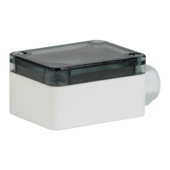
Page 14: Parts Identification
CONNECTOR, 6-PIN MODULAR 6540-0150 ENCLOSURE, POLYCARBONATE 6680-1015 SPACER, #4 X .375 SELF RETAINING 6021-1100 SCREW, PAN HD. #4-40 X .69 8527-C511-0A PC BOARD 6980-1046 CABLE, 6 COND. 26 GA. MODULAR, 74” LONG 8527-0570-0M Rev B APSWIFI Installation and Setup... -
Page 15: Statement Of Limited Warranty
STATEMENT OF LIMITED WARRANTY Detecto Scale warrants its equipment to be free from defects in material and workmanship as follows: Detecto warrants to the original purchaser only that it will repair or replace any part of equipment which is defective in material or workmanship for a period of one (1) year from date of shipment. - Page 16 8527-0570-0M Rev B APSWIFI Installation and Setup 8527-0570-0M Rev B APSWIFI Installation and Setup...
Need help?
Do you have a question about the APSWIFI and is the answer not in the manual?
Questions and answers