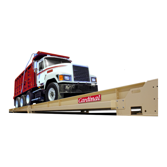
Summary of Contents for Cardinal ARMOR SMARTCELL
- Page 1 Top of the Document Digital Truck Scale Troubleshooting Guide 0330-1302-0M Rev A • Digital Truck Scale Troubleshooting Guide...
- Page 2 0330-1302-0M Rev A • Digital Truck Scale Troubleshooting Guide...
-
Page 3: Table Of Contents
COPYRIGHT All rights reserved. Reproduction or use, without expressed written permission, of editorial or pictorial content, in any manner, is prohibited. No patent liability is assumed with respect to the use of the information contained herein. DISCLAIMER While every precaution has been taken in the preparation of this manual, the Seller assumes no responsibility for errors or omissions. - Page 4 0330-1302-0M Rev A • Digital Truck Scale Troubleshooting Guide 0330-1302-0M Rev A • Digital Truck Scale Troubleshooting Guide...
-
Page 5: Introduction
Before calling Cardinal Scale for assistance, there are a few things to check first that can be done to get the system back up and running. Remember, that there is a logical explanation for all problems and for troubleshooting to be successful, it must be approached in a logical and rational manner. - Page 6 LOW VOLTAGE DETECTED CELL X, Cont. SOLUTION: I. If the system voltage is below 9 VDC, proceed as follows: J. First remove the White (V+ Bus) and Blue (V- Bus) wires from the Homerun cable on the DLC Card, and using a DVM, read the voltage on the connector. This should be minimum of 14 VDC on the 225DLC (11.5 VDC on the 825-DLC).
-
Page 7: Current Draw More Than 150% Of Capacity
CURRENT DRAW MORE THAN 150% OF CAPACITY SOLUTION: A. Cut the end off of an extra load cell cable and strip back the wires to make a test cable. B. Ensure the scale is powered up. C. Remove the End Node (terminator) from the last load cell in the loop, and connect the test cable to the port on the load cell where the End Node (terminator) was. -
Page 8: Load Cell X Not Responding
IDs and their corresponding scale locations (NOT the location in the data loop). C. If a Cardinal Digital Load Cell Simulator is available, remove the Homerun cable from the first load cell in the loop and attach it to the simulator. - Page 9 COMMUNICATIONS ERROR BETWEEN INDICATOR AND SCALE, Cont. SOLUTION: H. If a NEST is not available, proceed with the following instructions to check the Homerun cable for shorts: 1. Disconnect the Homerun cable from the load cell (Start Node). 2. Starting with one wire, check the resistance between it and each of the other wires one at a time.
-
Page 10: Load Cell X Has No Address
LOAD CELL X HAS NO ADDRESS SOLUTION: A. Go to the Scale Setup screen and enter the load cell ID in the correct scale location. COMMUNICATION ERROR BETWEEN LOADCELLS X AND Y SOLUTION: A. Use the NEST to test the suspect load cell cable for defects. B. -
Page 11: Load Cell Or Scale Communications Problems
LOAD CELL OR SCALE COMMUNICATIONS PROBLEMS SOLUTION: A. Go to the Diagnostics screen LOAD CELL COMMUNICATIONS ERRORS and observe the historical error counters for each load cell. B. Record these numbers. C. Press EXIT(?) to zero the counters on the 225D. For the 825D, press C)lear to zero the counters. - Page 12 Cardinal Scale Mfg. Co. 203 E. Daugherty, Webb City, MO 64870 USA Ph: 417-673-4631 or 1-800-641-2008 Fax: 417-673-2153 www.cardinalscale.com Technical Support: 1-866-254-8261 E-mail: tech@cardet.com Printed in USA 0330-1302-0M Rev A 03/19 0330-1302-0M Rev A • Digital Truck Scale Troubleshooting Guide...


Need help?
Do you have a question about the ARMOR SMARTCELL and is the answer not in the manual?
Questions and answers