Table of Contents
Advertisement
Advertisement
Table of Contents

Related Manuals for SOMFY SGA 6000


Summary of Contents for SOMFY SGA 6000
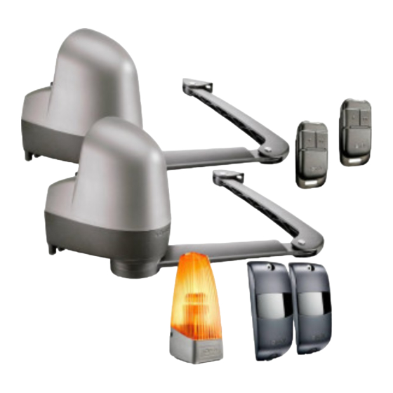
- Page 1 6000 MOTOR DRIVES 6000 INTÉGRAL FOR LEAF GATES 6000 INTÉGRAL +...
- Page 2 RADIO TOTAL + PIETON TOTAL FERMETURE AUTO SEQUENTIEL RAZ MEMOIRE STATUT RADIO TOTAL + PIETON TOTAL FERMETURE AUTO SEQUENTIEL RAZ MEMOIRE STATUT SGA 6000 INTEGRAL INTEGRAL +...
- Page 5 RADIO TOTAL + PIETON TOTAL FERMETURE AUTO 9 m : 2 x 1 mm² SEQUENTIEL RAZ MEMOIRE STATUT...
- Page 6 M10 x 150 M6 x 40 HM10 Not included in the kit...
-
Page 7: Table Of Contents
ContEnts Foreword ................safety instructions ..........Product description ..........Preliminary operations ........5-step installation : 1. Preparing and drilling gateposts ....12 2. Installing the motors ..........14 3. Mounting the arms ..........16 4. Electrical connections .......... 20 5. settings ................ -
Page 8: Foreword
Somfy’s approach. For further information on how to choose, purchase or install Somfy systems, please ask for advice at your DIY store or contact a Somfy advisor directly for help and assistance. Somfy UK Hotline : 0113 391 30 30... -
Page 9: Safety Instructions
Failure to follow these installation instructions may result in serious injury or damage to the equipment. Somfy shall not be held liable in this event. This device is not designed to be used by persons (including children) whose... -
Page 10: Product Description
Product description This product is intended for gates for residential houses (described on page 8). technical characteristics Supply voltage 230 V~ / Solar Motor type 24 V Motor power 120 W Maximum power consumption 600 W (with zone lighting) Consumption in standby mode 4.5 W Average frequency of use per day 20 cycles / day... - Page 11 Product description overall dimension of the sGA (in mm) Minimum clearance with gate open (in mm) Greater than or superior to 405 mm Ambient light detector Light detector The motor’s electronic unit is fitted with an ambient light detector which detects whether or not the cover is fitted. This means that settings mode is only available when the cover is removed.
-
Page 12: Preliminary Operations
Preliminary operations n Points to be checked before installing Checking your gate Your gate is in good condition: It will open and close normally without being forced. It remains horizontal as it is swinging open/closed. Opens inward. types of gates able to be motorised Your SGA can be used with any type of gate, provided its structure is sufficiently sturdy. - Page 13 Preliminary operations Checking the gateposts The gateposts must be sturdy and at least 25 cm wide. Otherwise, your gateposts may need servicing to ensure that they are firmly set in the ground and that the angle bracket is securely fastened. Quality of gateposts’...
- Page 14 Preliminary operations n Electrical pre-wiring To motorise your gate: • Install a 230 V electric supply on one of the gateposts, as near as possible to the SGA motor. • Interconnect the gateposts using the 2 x 1 cable provided (or two cables for photocells).
- Page 15 Preliminary operations Photocells (optional) The photocells are necessary for automatic-mode operation and for gates opening onto the public highway. • Wiring the photocells (see page 36) The 24-V input and information received from the contacts (receiving cell) must be under the cells. Drill the gateposts to pass the ducts through them.
-
Page 16: Preparing And Drilling Gateposts
Preparing and drilling gateposts n steps : o Dimension measurement. o Marking the AM and AH baselines. o Drilling the gateposts. o Dimension measurement The type of gate determines where the motors are to be placed. Measure the dimensions described below to determine their position on the gateposts: For these measurements, the leaves and their hinges are supposed to be on the same axis. - Page 17 Preparing and drilling gateposts o Marking the AM and AH baselines. Carry dimension B over and trace a vertical Trace the horizontal line (AH) onto the baseline (AM) onto the gateposts. post, halfway up the bracket. o Drilling the gateposts. Position the template at the intersection of baselines AM and AH.
-
Page 18: Installing The Motors
Place the motor which includes the electronic control unit on the gatepost where the power supply is located. o Applying the sealants. For dependability, SOMFY advises that you fasten the motor using a chemical sealant. Position the motor on the gatepost Remove the motor. Place the 4 chemical... - Page 19 Installing the motors o Installing the motors. Position the motor by fastening it onto the Check that the motors are level. Continue lower threaded rods using the washers tightening if necessary. and nuts. Finish mounting the motor on the upper threaded rods, using the washers and nuts. self-check before the next step Have you checked that the motor is perfectly horizontal?
-
Page 20: Mounting The Arms
Mounting the arms n steps : o Assembling the arms. o Mounting the arms on the motors. o Mounting the arms on the leaves. o Assembling the arms. Engage the two arms. Fold the arms so that the inner grooves Insert the short shaft. - Page 21 Mounting the arms Installing the flexible ring in the arm Insert the flexible ring into the arm (2). Snap the covers (1) into place on each side bosses of the arm, making sure that their bosses are fully inserted into the arm’s grooves. Installing the fastening lug Mount the fastening lug onto the arm and insert the long shaft.
- Page 22 Mounting the arms o Mounting the arms on the leaves. Mounting the arms onto the gate requires drilling holes in the leaves. Complete the following steps: Check that the motors are in the unlocked position . Check that the gate is closed and in contact with the stop. open the arm hinges completely onto the leaf bracket.
- Page 23 Mounting the arms • Remove the arm from the fastening lug. • Using a mallet, drive the bolts all the way into the gate. • Assemble the fastening lug on the leaves, then re-install the arms into the fastening lug. self-check before the next step Did you open the arm hinge completely when mounting the arms on the leaf brackets?
-
Page 24: Electrical Connections
Electrical connections n steps : o Installing the grommets. o Connecting the two motors. o Connecting the antenna. o Connecting the mains power cord. o Locking the arms. o Installing the grommets. Mount the grommets onto the two motors. - Page 25 Electrical connections o Connecting the two motors. The two motors must be interconnected before they are connected to the mains. Motor M1 must be installed on the post of the leaf which opens first and closes last. Case 1 : Motor M1 operates the left leaf, which opens first and closes last: Blue Brown Blue...
- Page 26 Electrical connections o Connecting the antenna. For best performance, the antenna must be positioned properly. never cross the antenna’s wire. o Connecting the mains power cord (230 V only ; for a connection to a solar power supply, see page 42). Connect the earth wire: Connect the phase and the neutral:...
-
Page 27: Settings
Storing the remote controls. Do not block the light sensor using the remote control (see page 7). <0,5s Place the remote control under the word «Somfy». Briefly press any button on the remote control. RADIO indicator lights up then goes out. - Page 28 settings o Gate travel learning process. For use with the cells, these must be installed and aligned correctly before the learning process (see pages 35 to 36). the gate must be closed to carry out the learning process. The motor’s electronics automatically store: •...
- Page 29 settings At the end of these 2 steps, the STATUS indicator is continuously lit. If the STATUS indicator is flashing, refer to the troubleshooting section on page 33. This must be a full cycle (2 complete and uninterrupted openings/closings). If it is interrupted, the process is simply postponed, and will resume the next time the gate is opened.
- Page 30 operation n operation in sequential mode All the programmed 2- or 4-button remote controls have the same mode of operation. Successive presses of the same control button will lead to the following movements of the gate: open, stop, Close, stop, open etc. Automatic opening The gate is opened automatically by pressing the remote control.
- Page 31 (see description and wiring information on pages 35 and 36). Somfy recommends the installation of an orange light (see description and wiring information on pages 37 and 38) and a lighting area (see wiring on page 38).
- Page 32 operation n operation of the 3-button remote controls or control points STOP The gate is stopped by The gate is opened by The gate is closed by pressing the central button. pressing the up button. pressing the down button. Three-button remote controls or control points cannot be used to open the gate for pedestrian access.
-
Page 33: Usage
Adding 3-button remote controls <0,5s Place the remote control under the word «Somfy» Briefly press the up or down button on the remote control RADIO indicator lights up then goes out. n Entering the settings menu Do not block the light sensor with the remote control (see page 7). - Page 34 Advanced parameter setting n Activating totAL + PEDEstRIAn mode Press the right-hand button. Access the settings TOTAL+PEDESTRIAN indicator lights up menu (see page continuously, then flashes. 29). To switch to TOTAL mode only, proceed in the same way; the TOTAL+PEDESTRIAN indicator goes off then flashes.
- Page 35 Advanced parameter setting n Clearing the remote controls and all settings Access the settings menu (see page 29). Press the left-hand button repeatedly until the RESET indicator flashes. Press the right-hand button until the RESET indicator lights up. Release the button. STATUS indicator flashes.
-
Page 36: Troubleshooting
troubleshooting n the motors do not respond to actions on the remote control the remote control range is reduced - Check the remote control battery The service life of the battery is generally 2 years. Used batteries must be returned to the distributor or disposed of at a waste sorting centre Remove the clip Lift the Replace the... - Page 37 Reconnect the cells (see page 36). Repeat the quick commissioning process (see pages 23 to 25). n other faults For all technical or commercial advice, please contact our Somfy Hotline advisors from Monday to Saturday 9:00 - 18:00 on 0113 391 30 30.
-
Page 38: Accessories
Accessories - Description and connections n section des câbles par type d’accessoire... - Page 39 Accessories - Description and connections 2400939 n Cells The cells are used to stop and reverse the closing movement of the gate when an obstacle is detected IP44 2 x 0.75 mm + 60°C (cells blocked). 24 Vac/dc - 20°C Note: If the gate is closed and the cells are blocked, HO5 RR-F the gate will not open.
- Page 40 Accessories - Description and connections 1 2 3 5 1 2 3 5 1 2 1 2 3 5 Yellow label (BUS) 3 4 3 4 X X to check the cell alignment, the transmitter cell cover must be fitted but not the receiver cell cover.
- Page 41 Accessories - Description and connections 2400596 n orange light The orange light warns that the motor is Ø22 + 60°C about to operate. It starts to flash 2 seconds before the gate - 20°C begins to move. 24 V 10 Watt max Installing the orange light IPX4 2 x 0.75 mm...
- Page 42 Accessories - Description and connections Wiring the orange light Connect the orange light to terminals 7 and 8 (orange «FLASH» label) on the electronic unit. n Area lighting Connect the area lighting to terminals 13 and 14 (white «LIGHT» label) on the electronic unit. For solar power, see page 42.
- Page 43 Accessories - Description and connections Battery wiring and fitting Connect the battery to the terminal provided for this purpose (grey «BATT» label) on the electronic unit. 2400597 n Key switch this accessory is not compatible with solar power. We recommend the external radio code keypad (page 41). Connect the key switch to terminals 3 and 4 (yellow «BUS»...
- Page 44 Accessories - Description and connections 2400581 n Wired keypad this accessory is not compatible with solar power. We recommend the external radio code keypad (page 41). – H P2 M P1 T3 C3 R3 T2 C2 R2 T1 C1 R1 V Connect: - T1 and C1 of the keypad to terminals 3 and 4 (yellow «BUS» label) on the electronic unit - V and V of the keypad to terminals 5 and 6 (black «24V»...
- Page 45 Accessories - Description and connections 2400625 n External radio code keypad 2400549 n 2 button remote control CODE 2400576 n 4 button remote control 2400660 n Multi-application remote control...
- Page 46 solar power never connect the motor to the mains supply and the solar power supply at the same time. this may damage the electronic control unit of the motor. To limit the energy consumption of the motor, we recommend : - to use the automatic mode (see page 30 to activate the AUTO CLOSE mode), - and to close the gate after using it.
- Page 47 solar power n Connection to the solar power supply Connect the solar power supply cable to the grey «BATT» terminal on the motor’s electronic unit n Area lighting connection Connect the area lighting to terminals 5 and 6. 24V - 15W...
- Page 48 SOMFY LTD Moorfield Road Yeadon Leeds West Yorkshire LS19 7BN Tel. 0113 391 3030 Fax. 0113 391 3010...
Need help?
Do you have a question about the SGA 6000 and is the answer not in the manual?
Questions and answers