Table of Contents
Advertisement
Quick Links
Reference Manual
(Hardware)
Digital Input/Output Module
CPS-MC341-DS2-111
CPS-MC341-DS2-911
CONTENTS
Introduction .................................................................. 4
Safety Precautions .................................................... 12
Product Nomenclature and Function ............... 21
Setup ............................................................................. 35
Installation ................................................................... 41
Appendix ...................................................................... 61
Optional Products .................................................... 71
Customer Support and Inquiry ............................ 73
Index .............................................................................. 75
Advertisement
Table of Contents

Related Manuals for Contec CONPROSYS CPS-MC341-DS2-111


Summary of Contents for Contec CONPROSYS CPS-MC341-DS2-111
- Page 1 Reference Manual (Hardware) Digital Input/Output Module CPS-MC341-DS2-111 CPS-MC341-DS2-911 CONTENTS Introduction ..............4 Safety Precautions ............ 12 Product Nomenclature and Function ....21 Setup ................35 Installation ..............41 Appendix ..............61 Optional Products ............ 71 Customer Support and Inquiry ......73 Index ................
-
Page 2: Table Of Contents
Table of Contents Introduction ............... 4 1. Related Manuals ..............................5 2. Check the Firmware Version ..........................6 3. About the Product ..............................7 4. Interface Within ............................... 8 5. Features ..................................9 1. Hardware features ............................9 2. Software Features ............................10 6. - Page 3 Table of Contents 1. Install the Product ............................... 42 1. Installation Conditions ..........................42 2. Mounting on/Removing from a DIN Rail .................... 44 3. Mounting on the Wall ..........................46 2. Connecting to an External Device ......................... 47 3. Cable Connection ..............................49 1.
-
Page 4: Introduction
Introduction This section provides necessary information of the product such as the outline, bundled items and manuals before actual use. — 4 —... -
Page 5: Related Manuals
(Printed matter) package. and describes the precautions. Setup Manual Download from Read this when setting up the This describes the required items for the Contec product. setup and configuration procedure. website (PDF) Reference Manual Download from Read this when operating the... -
Page 6: Check The Firmware Version
Before start using the product, visit our website to check the firmware version and update to the latest one if necessary. Updating firmware to the latest version will resolve troubles and stabilize the operation. https://www.contec.com/download/ Download *Refer to the "Reference Manual (Software)" for the details of the firmware updating. -
Page 7: About The Product
— — Introduction CPS-MC341-DS2-111, CPS-MC341-DS2-911 Reference Manual (Hardware) 3. About the Product This product is a M2M controller with isolated CAN, isolated RS-422A/485, isolated digital input/output, and LAN interface. The CPS-MC341-DS2-111 contains no battery for RTC, and the CPS-MC341-DS2-911 contains one battery for RTC within. -
Page 8: Interface Within
— — Introduction CPS-MC341-DS2-111, CPS-MC341-DS2-911 Reference Manual (Hardware) 4. Interface Within This product is a M2M controller with the following interfaces. SD Card Analog Input Analog Output Digital Input Digital Output Slot [Current] [Current] Analog Output 3GSIM Analog Input Counter RS-422A/485 RS-232C (Standard SIM)... -
Page 9: Features
— — Introduction CPS-MC341-DS2-111, CPS-MC341-DS2-911 Reference Manual (Hardware) 5. Features 1. Hardware features Compact design Compact design, 188.0(W) × 78.0(D) × 30.5(H), features flexibility in installation. Adaptable to a temperature range between -20 and +60°C The product is capable of operating in the temperature between -20 and + 60°C. It can be installed in the various environments. ... -
Page 10: Software Features
CPS-MC341-DS2-111, CPS-MC341-DS2-911 Reference Manual (Hardware) Choice of a battery with a longer life (for CPS-MC341-DS2-911). With a choice of a long-life battery, the Contec is creating longer lasting products. 2. Software Features Measurement and Upload Upload measured data of a sensor and also collected data from PLC to the Cloud server. -
Page 11: Product Configuration List
*1 One of the followings - CPS-MC341-DS2-111, CPS-MC341-DS2-911 *This product is verified in conformity with our recommended power supply. In case you use other power supplies, thus, it may not be able to fulfil certification requirements. Please see the Contec website regarding power supply recommendation (https://www.contec.com/). -
Page 12: Safety Precautions
Safety Precautions Understand the following definitions and precautions to use the product safely. Never fail to read them before using the product. — 12 —... -
Page 13: Safety Information
— — Safety Precautions CPS-MC341-DS2-111, CPS-MC341-DS2-911 Reference Manual (Hardware) 1. Safety Information This document provides safety information using the following symbols to prevent accidents resulting in injury or death and the destruction of equipment and resources. Understand the meanings of these labels to operate the equipment safely. DANGER DANGER indicates an imminently hazardous situation which, if not avoided, will result in death or serious injury. -
Page 14: Handling Precautions
— — Safety Precautions CPS-MC341-DS2-111, CPS-MC341-DS2-911 Reference Manual (Hardware) 2. Handling Precautions DANGER Do not use the product in locations exposed to a flammable or corrosive gas. It may cause explosion, fire, electrical shock, or malfunction. Do not allow the device to come into contact with foreign substances (metal particles, ... - Page 15 When removing connectors or cables, always unplug the power cables and confirm the LEDs are turned off. Do not modify the product. CONTEC will bear no responsibility for any problems, etc., resulting from modifying the product. In the event of failure or abnormality (foul smells or excessive heat generation), unplug the ...
- Page 16 Regardless of the foregoing statements, CONTEC is not liable for any damages whatsoever (Including damages for loss of business profits) arising out of the use or inability to use this CONTEC product or the information contained herein.
- Page 17 Lors du dépôt de connecteurs ou de câbles, toujours débrancher les câbles d’alimentation de l’unité centrale et confirmer la mise hors tension des DEL. Ne pas modifier le produit. CONTEC ne pourra être tenue responsable de tout problème, etc., issu de la modification du produit.
- Page 18 Lors d’un fonctionnement du produit sans interruption, s’assurer de lire le manuel du site Web CONTEC et d’assimiler le contenu. Lorsque le produit est utilisé à un endroit influencé par une surintensité ou une surtension ...
-
Page 19: Fcc Part15 Subpart B Class A Notice
— — Safety Precautions CPS-MC341-DS2-111, CPS-MC341-DS2-911 Reference Manual (Hardware) 1. FCC PART15 Subpart B Class A Notice NOTE This equipment has been tested and found to comply with the limits for a Class A digital device, pursuant to part 15 of the FCC Rules. These limits are designed to provide reasonable protection against harmful interference when the equipment is operated in a commercial environment. -
Page 20: Battery Handling And The Storage In Eu Signatory
— — Safety Precautions CPS-MC341-DS2-111, CPS-MC341-DS2-911 Reference Manual (Hardware) 3. Battery handling and the storage in EU signatory This symbol mark is for EU countries only. This symbol mark is according to the directive 2006/66/EC Article 20 Information for end-users and Annex II. -
Page 21: Product Nomenclature And Function
Product Nomenclature and Function This section describes product component names and their functions, pin assignment of each connector. — 21 —... -
Page 22: Nomenclature Of Product Components
— — Product Nomenclature and Function CPS-MC341-DS2-111, CPS-MC341-DS2-911 Reference Manual (Hardware) 1. Nomenclature of Product Components Component names of the product are shown in the figure below. Iso late d C AN 12-24VDC Half Full Half Full COM A LAN A LAN B Name Function... -
Page 23: Description Of Product Components
To check the supplied connector type, refer to “Appendix - Connector Check”. Pin Assignment Pin No. Signal Name V-(GND) V+(12-24VDC) 2. Debug Connector Do not use this. 3. SD Card Slot Insert the SD card to store such as data. *Use the Contec SD card "SD-4GB-A (4GB)". — 23 —... -
Page 24: Can Port
— — Product Nomenclature and Function CPS-MC341-DS2-111, CPS-MC341-DS2-911 Reference Manual (Hardware) 4. CAN Port This product has 1 channel of CAN (Controller Area Network) port. The CAN is recognized as two ports on kernel. With this product, only CAN0 can be used. 9-pin D-SUB (Male) No.4-40UNC inch nut Pin Assignment... -
Page 25: Led Indicator
— — Product Nomenclature and Function CPS-MC341-DS2-111, CPS-MC341-DS2-911 Reference Manual (Hardware) 5. LED Indicator Status of the product is indicated by ON/OFF and flashing of LED. The meaning of each LED is described below. Color and Description Color Display Description Green Power has been supplied. -
Page 26: Dip Switch
— — Product Nomenclature and Function CPS-MC341-DS2-111, CPS-MC341-DS2-911 Reference Manual (Hardware) 8. DIP Switch SW1, SW2 DIP switch for system setup and RS-422A/485 setup of COM A. The factory default of all switches are set to “OFF”. R S-232 C C O M B 2 3 4 1 2 3 4 5 6... - Page 27 — — Product Nomenclature and Function CPS-MC341-DS2-111, CPS-MC341-DS2-911 Reference Manual (Hardware) DIP Switch Bit No. ON/OFF Description SW Number 1, 2– ON: Enable the Terminator (Terminator value 120Ω) Disable the Terminator SW Number 1, 2– ON: Enable the Terminator (Terminator value 120Ω) Disable the Terminator Unused.
-
Page 28: Lan Port
— — Product Nomenclature and Function CPS-MC341-DS2-111, CPS-MC341-DS2-911 Reference Manual (Hardware) 9. LAN Port This product has 2 ports of Ethernet. As the LAN port of this product is set in HUB mode, it is recognized as one port from OS. Ethernet Hub function in this product is the switching hub. - Page 29 — — Product Nomenclature and Function CPS-MC341-DS2-111, CPS-MC341-DS2-911 Reference Manual (Hardware) CAUTION HUB mode of this product might be slower than other standard switching HUB products. If a large amount of data or high-speed response is requested, an external switching HUB ...
-
Page 30: Digital Output Connecter
— — Product Nomenclature and Function CPS-MC341-DS2-111, CPS-MC341-DS2-911 Reference Manual (Hardware) 10. Digital Output Connecter This product has 8 channels of digital output. Use the 10-pin connector included in the package. Connector type: DEGSON 15EDGK-3.5-10P-14-1000AH (or equivalent) *The type of connectors in the package differs depending on the period of manufacturing. To check the supplied connector type, refer to “Appendix - Connector Check”. -
Page 31: Digital Input Connecter
— — Product Nomenclature and Function CPS-MC341-DS2-111, CPS-MC341-DS2-911 Reference Manual (Hardware) 11. Digital Input Connecter This product has 8 channels of digital input. Use the 10-pin connector, included in the package, to connect to external power. Connector type: DEGSON 15EDGK-3.5-10P-14-1000AH (or equivalent) *The type of connectors in the package differs depending on the period of manufacturing. -
Page 32: Rs-422A/485 Connector
— — Product Nomenclature and Function CPS-MC341-DS2-111, CPS-MC341-DS2-911 Reference Manual (Hardware) 12. RS-422A/485 Connector This product has 1 port (COMA) of RS-422A/485 communication. Use the 5-pin connector, included in the package, to connect to external power. Connector type: DEGSON 15EDGK-3.5-05P-14-1000AH (or equivalent) *The type of connectors in the package differs depending on the period of manufacturing. -
Page 33: Other Functions
— — Product Nomenclature and Function CPS-MC341-DS2-111, CPS-MC341-DS2-911 Reference Manual (Hardware) 3. Other Functions 1. Digital Filter This product can apply a digital filter to every input pin, thereby preventing wrong recognition of input signals from being affected by noise or chattering. ... - Page 34 — — Product Nomenclature and Function CPS-MC341-DS2-111, CPS-MC341-DS2-911 Reference Manual (Hardware) Digital Filter Setting Time Set the digital filter time to 0 - 20 (00h - 14h). Setting the digital filter time to 0 disables the function of filtering (0 is set as default and upon turning on the power) Setting Data (n) Digital Filter Time...
-
Page 35: Setup
Setup This section describes how to set switches and an antenna that are necessary to operate the product. — 35 —... -
Page 36: Set Data Transfer Mode
— — Setup CPS-MC341-DS2-111, CPS-MC341-DS2-911 Reference Manual (Hardware) 1. Set Data Transfer Mode With the DIP switch (SW1, SW2), data transfer mode can be changed (half-duplex or full-duplex). Set the data transfer mode in accordance with a device which you are connecting to. 1. - Page 37 — — Setup CPS-MC341-DS2-111, CPS-MC341-DS2-911 Reference Manual (Hardware) DIP Switch Bit No. ON/OFF Description Enable the TX Terminator Disable the TX Terminator Enable the RX Terminator Disable the RX Terminator Internal connection state of TX+ and RX+: Short (Half Duplex) Internal connection state of TX+ and RX+: Open (Full Duplex) Internal connection state of TX- and RX-: Short (Half Duplex) Internal connection state of TX- and RX-: Open (Full Duplex)
- Page 38 — — Setup CPS-MC341-DS2-111, CPS-MC341-DS2-911 Reference Manual (Hardware) Terminator(Bit 1) Terminator(Bit 2) This Product External Device Terminator(Bit 2) Terminator(Bit 1) Use the terminator inside Set the terminator outside 2 3 4 1 2 3 4 5 6 2 3 4 1 2 3 4 5 6 DIP Switch Bit No.
-
Page 39: Insert Sd Card
— — Setup CPS-MC341-DS2-111, CPS-MC341-DS2-911 Reference Manual (Hardware) 2. Insert SD Card Unfasten the screw of the cover. (Card cover is attached to the product upon shipping). Slide the card cover to remove it. With the chipped edge of the SD card is in the position shown below, insert the card all the way into the slot. - Page 40 — — Setup CPS-MC341-DS2-111, CPS-MC341-DS2-911 Reference Manual (Hardware) Fasten with a screw. *Reverse the procedure described in the "Insert SD card "to remove the card. — 40 —...
-
Page 41: Installation
Installation This section describes how to mount the product on a DIN rail or on the wall, and to connect to an external device with a cable. — 41 —... -
Page 42: Install The Product
— — Installation CPS-MC341-DS2-111, CPS-MC341-DS2-911 Reference Manual (Hardware) 1. Install the Product 1. Installation Conditions Installation Orientation Install the product in the orientations shown below (0 °C). Other orientations may cause problems such as malfunctions due to inadequate heat dissipation. DIN rail Mounting Wall Mounting Operating ambient temperature should be between -20 °C and +55 °C when the product is installed... - Page 43 — — Installation CPS-MC341-DS2-111, CPS-MC341-DS2-911 Reference Manual (Hardware) Ambient Temperature The ambient temperature is decided from the multiple measurement points which are a 50mm- distance from the product. During the operation, adjust the air current to make certain that the temperatures measured in the points stay within the specified temperature.
-
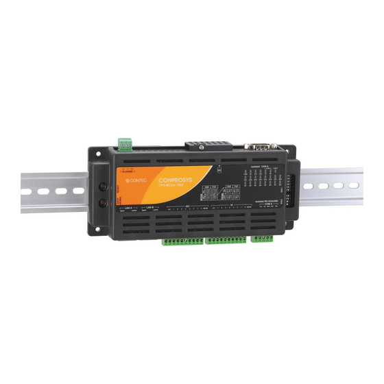
Page 44: Mounting On/Removing From A Din Rail
— — Installation CPS-MC341-DS2-111, CPS-MC341-DS2-911 Reference Manual (Hardware) ATTENTION Remarquez que même si la température ambiante se situe dans la plage de température spécifiée, une défaillance opérationnelle peut survenir si un autre appareil à proximité émet beaucoup de chaleur. Le rayonnement influence la hausse de température du produit. N’installez pas le produit dans un espace entièrement scellé... - Page 45 — — Installation CPS-MC341-DS2-111, CPS-MC341-DS2-911 Reference Manual (Hardware) Push the hooks up to lock the product on the DIN rail. How to Remove Pull down the hooks to unlock. If the hooks are stuck, use a slotted screwdriver to unlock. Fixed hooks (1).
-
Page 46: Mounting On The Wall
— — Installation CPS-MC341-DS2-111, CPS-MC341-DS2-911 Reference Manual (Hardware) 3. Mounting on the Wall Appropriate screws (fit into φ3.5 hole) are required to install the product on the wall. The commercial screws can be purchased individually. Get the screws fit into φ3.5 hole and set the product. -
Page 47: Connecting To An External Device
— — Installation CPS-MC341-DS2-111, CPS-MC341-DS2-911 Reference Manual (Hardware) 2. Connecting to an External Device Use the supplied connector plug to connect the product to an external device. The following example describes how to make the connecting cable with a 3-pin connector. Connection Cable The supplied connector... - Page 48 — — Installation CPS-MC341-DS2-111, CPS-MC341-DS2-911 Reference Manual (Hardware) ATTENTION Ne tirez pas sur le câble de la fiche du connecteur pour retirer la fiche, vous risquez de briser le fil. Saisissez toujours le connecteur pour le retirer. Le couple de serrage pour le connecteur fourni est indiqué ci-dessous. ...
-
Page 49: Cable Connection
— — Installation CPS-MC341-DS2-111, CPS-MC341-DS2-911 Reference Manual (Hardware) 3. Cable Connection 1. Power Power Cable Use the power cable described below. Cable Twisted pair cable (when using a single wire, twist V+ wire and V- wire) Cable Diameter AWG24 - 16(0.2mm - 1.25mm Cable Length Within 3 meters... -
Page 50: Lan
— — Installation CPS-MC341-DS2-111, CPS-MC341-DS2-911 Reference Manual (Hardware) If the maximum output current of the external power supply is smaller than the maximum consumption current of the product, the abnormal operations might occur due to the inrush current at the start-up time or the load fluctuation. The aging external power supply could cause a start-up failure About a caution mark on the product: Please use copper wires that tolerate the... -
Page 51: Rs-422A/485
— — Installation CPS-MC341-DS2-111, CPS-MC341-DS2-911 Reference Manual (Hardware) 3. RS-422A/485 RS-422A/485 Cable Use the RS-422A/485 cable described below. Cable Twisted pair cable with the shield Cable AWG28-16(0.08mm - 1.25mm Diameter Cable Length Affected by the communication speed (baud rate) between the product and the external device. - Page 52 — — Installation CPS-MC341-DS2-111, CPS-MC341-DS2-911 Reference Manual (Hardware) Baud Rate See the table below for the baud rate that can be set with the product. Error rate differs depending on the set baud rate. Baud Rate (bps) Error (%) 0.00 0.00 0.00...
- Page 53 — — Installation CPS-MC341-DS2-111, CPS-MC341-DS2-911 Reference Manual (Hardware) Connecting to an external device Connect the product in accordance with the specification of the external device. RS-422A/485 5-pin connector TX+ TX- RX+ RX- SG External device - Full Duplex Full duplex needs three or more sets of twisted-pair. Two sets are for a signal line, other free line(s) is (are) for the signal ground (SG).
- Page 54 — — Installation CPS-MC341-DS2-111, CPS-MC341-DS2-911 Reference Manual (Hardware) Connecting to an external device Connect the product in accordance with the specification of the external device. RS-422A/485 5pin-connector TX+ TX- RX+ RX- SG External device RX+ RX- TX+ TX- Notes on the Shield Connection Ground the shield to the frame ground (FG) of the external device.
- Page 55 — — Installation CPS-MC341-DS2-111, CPS-MC341-DS2-911 Reference Manual (Hardware) ATTENTION Ne tirez pas sur le câble de la fiche du connecteur pour retirer la fiche, vous risquez de briser le fil. Saisissez toujours le connecteur pour le retirer. Le couple de serrage pour le connecteur fourni est indiqué ci-dessous. ...
-
Page 56: Can
— — Installation CPS-MC341-DS2-111, CPS-MC341-DS2-911 Reference Manual (Hardware) 4. CAN CAN Cable Use CAN (Controller Area Network) cable described below. Cable Use copper wires that tolerate a temperature of 75 °C or higher. Cable Diameter Select the diameter that can match the used connector. *Refer to "CAN Port"... -
Page 57: Digital Input
— — Installation CPS-MC341-DS2-111, CPS-MC341-DS2-911 Reference Manual (Hardware) 5. Digital Input Digital Input Use the Digital Input cable described below. Cable Use copper wires that tolerate the temperature of 75 °C and higher. Cable Diameter AWG28 - 16 Cable Length The length differs depending on the actual use environment. -
Page 58: Digital Output
— — Installation CPS-MC341-DS2-111, CPS-MC341-DS2-911 Reference Manual (Hardware) 6. Digital Output Digital Output Cable Use the Digital Output cable described below Cable Use copper wires that tolerate the temperature of 75 °C and higher. Cable AWG28 - 16 Diameter Cable Length The length differs depending on the actual use environment. - Page 59 — — Installation CPS-MC341-DS2-111, CPS-MC341-DS2-911 Reference Manual (Hardware) Example of connecting to the LED The corresponding LED lights up when you output "1" into the appropriate bit. The corresponding LED turns off when you output "0" into the appropriate bit. Output pin (+) External LED 5.1kΩ...
- Page 60 — — Installation CPS-MC341-DS2-111, CPS-MC341-DS2-911 Reference Manual (Hardware) ATTENTION Ne tirez pas sur le câble de la fiche du connecteur pour retirer la fiche, vous risquez de briser le fil. Saisissez toujours le connecteur pour le retirer. Le couple de serrage pour le connecteur fourni est indiqué ci-dessous. ...
-
Page 61: Appendix
Appendix This section lists the specifications and the physical dimensions of the product, and the details of model name. — 61 —... -
Page 62: Specifications
— — Appendix CPS-MC341-DS2-111, CPS-MC341-DS2-911 Reference Manual (Hardware) 1. Specifications 1. Specifications Function Specifications Item CPS-MC341-DS2-111 CPS-MC341-DS2-911 ARM Cortex-A8 600MHz Memory On Board 512MB DDR3 SDRAM On-Board 32MB NOR Flash for OS Transmission standard 10BASE-T/100BASE-TX The number of channels Connector RJ-45 Connector Speed (Yellow), Link/Act (Green) RS-422A/485... - Page 63 — — Appendix CPS-MC341-DS2-111, CPS-MC341-DS2-911 Reference Manual (Hardware) Item CPS-MC341-DS2-111 CPS-MC341-DS2-911 Open circuit impedance 10kΩ and more Short circuit impedance 500Ω or less Input resistance 3.3kΩ Response time Within 200μsec Interrupt 8 interrupt input signals are arranged into a single output of interrupt signal.
- Page 64 — — Appendix CPS-MC341-DS2-111, CPS-MC341-DS2-911 Reference Manual (Hardware) *1 Data 0 corresponds to High level and Data 1 corresponds to Low level. *2 Use power cable within 3meters. *3 Commercial screws are required (fit into φ3.5 hole). Installation Environment Requirements Item Description Operating ambient temperature...
-
Page 65: Power Requirements
Quand vous remettez le courant, laissez le produit hors tension pendant au moins une seconde (ou plus) du délai hors tension. Lorsque vous utilisez le produit avec CPS-PWD-15AW12-01 (de CONTEC), le délai permis de chute instantanée de tension sera de 20 millisecondes ou moins. -
Page 66: Physical Dimensions
— — Appendix CPS-MC341-DS2-111, CPS-MC341-DS2-911 Reference Manual (Hardware) 2. Physical Dimensions 1. Product Isolated CAN A 12-24VDC H alf Full H alf Full Isolated RS-422A/485 COM A LAN A LAN B (154) 4-φ3.5 [mm] — 66 —... -
Page 67: The Details Of Model Name
— — Appendix CPS-MC341-DS2-111, CPS-MC341-DS2-911 Reference Manual (Hardware) 3. The Details of Model Name Details of the model name are described below. CPS - MC 3 4 1 - DS2 - 9 1 1 8 9 CONPROSYS Series Item Description Model Gateway Integrated Type Model ARM Cortex A8... -
Page 68: Battery Disposal
— — Appendix CPS-MC341-DS2-111, CPS-MC341-DS2-911 Reference Manual (Hardware) 4. Battery Disposal 1. Battery Specification The battery details are as follows: Item Description Type Lithium primary battery Model BR2330A/HD Maker Panasonic Nominal Voltage Nominal Volume 255mAh 2. How to remove the battery When disposing of the product, follow the instruction below and remove the battery. -
Page 69: Connector Check
— — Appendix CPS-MC341-DS2-111, CPS-MC341-DS2-911 Reference Manual (Hardware) 5. Connector Check The maker of connectors in the package or embedded in the product differs depending on the period of manufacturing. The maker and types of the connectors can be checked by the color. Maker, Type CAUTION See the table below for maker, type, and tightening torque value of the connectors to check and... - Page 70 — — Appendix CPS-MC341-DS2-111, CPS-MC341-DS2-911 Reference Manual (Hardware) Vérification du connecteur Selon la période de fabrication, le fabricant des connecteurs de l’emballage ou intégré au produit varie. Il est possible de confirmer le fabricant et les types de connecteur par la couleur. le nom du fabricant et le type ATTENTION Consultez le tableau ci-dessous pour connaître le fabricant, le type de connecteur et le couple de...
-
Page 71: Optional Products
Optional Products This section lists optional items that can be used along with the product. — 71 —... -
Page 72: Optional Products
DIN rail fitting power CPS-PWD-15AW12-01 Fitting power supply 15W supply (Input: 100-240VDC, Output: 12VDC 1.3A) SD Card SD-4GB-A SD card 4GB Magnet CPS-MAG01-4 Magnet (Four Piece Set) Visit the Contec website for the latest optional products. https://www.contec.com/ Website — 72 —... -
Page 73: Customer Support And Inquiry
Customer Support and Inquiry CONTEC provides the following support services for you to use CONTEC products more efficiently and comfortably. — 73 —... -
Page 74: Services
— Customer Support and Inquiry CPS-MC341-DS2-111, CPS-MC341-DS2-911 Reference Manual (Hardware) 1. Services CONTEC offers the useful information including product manuals that can be downloaded through the CONTEC website. Download https://www.contec.com/download/ You can download updated driver software, firmware, and differential manuals in several languages. -
Page 75: Index
Index — 75 —... - Page 76 — — Index CPS-MC341-DS2-111, CPS-MC341-DS2-911 Reference Manual (Hardware) Revision History MONTH YEAR Summary of Changes December 2015 The First Edition April 2018 Changed the layout of the manual. September 2018 Additional information was listed due to some parts change. — 76 —...
- Page 77 3-9-31, Himesato, Nishiyodogawa-ku, Osaka 555-0025, Japan https://www.contec.com/ No part of this document may be copied or reproduced in any form by any means without prior written consent of CONTEC CO., LTD. CPS-MC341-DS2-111, CPS-MC341-DS2-911 Reference Manual (Hardware) NA04575 (LYTJ306) 08302019_rev6 [12242018]...
Need help?
Do you have a question about the CONPROSYS CPS-MC341-DS2-111 and is the answer not in the manual?
Questions and answers