Table of Contents
Advertisement
Quick Links
Reference Manual
(Hardware)
Serial I/O Module RS-422A/485
CPSN-COM-1PD
CONTENTS
Introduction .................................................................. 3
Safety Precautions ...................................................... 9
Product Nomenclature and Function ............... 15
Installation ................................................................... 23
Appendix ...................................................................... 33
Optional Products .................................................... 38
Customer Support and Inquiry ............................ 40
Advertisement
Table of Contents

Related Manuals for Contec CONPROSYS nano CPSN-COM-1PD


Summary of Contents for Contec CONPROSYS nano CPSN-COM-1PD
- Page 1 Reference Manual (Hardware) Serial I/O Module RS-422A/485 CPSN-COM-1PD CONTENTS Introduction ..............3 Safety Precautions ............9 Product Nomenclature and Function ....15 Installation ..............23 Appendix ..............33 Optional Products ............ 38 Customer Support and Inquiry ......40...
-
Page 2: Table Of Contents
Table of Contents Introduction ............... 3 1. Related Manuals ..............................4 2. Check the Firmware Version ..........................5 3. About the Product ..............................6 4. Features ..................................7 5. Product Configuration List ..........................8 Safety Precautions ............. 9 1. Safety Information ............................... 10 2. Handling Precautions ............................11 1. -
Page 3: Introduction
Introduction This section provides necessary information of the product such as the outline, bundled items and manuals before actual use. — 3 —... -
Page 4: Related Manuals
Reference Manual for I/O Download from Read this when operating the This describes the hardware aspects Module (Hardware) the Contec I/O module with CPU Unit. such as functions and settings of the website (PDF) I/O module. CPU Unit Reference... -
Page 5: Check The Firmware Version
Before you start using the product, visit our website to check the firmware version of the CPU unit and update to the latest one if necessary. Updating firmware to the latest version will resolve troubles and stabilize the operation. https://www.contec.com/download/ Download Refer to the "Reference Manual (Software)" for the details of the firmware updating. -
Page 6: About The Product
— — Introduction CPSN-COM-1PD Reference Manual (Hardware) 3. About the Product This product is an expansion I/O module that adds a COM port complied with RS-422A/485 to the CPU unit of the CONPROSYS nano series. One channel of RS-422A/485 communication port is supplied. —... -
Page 7: Features
— — Introduction CPSN-COM-1PD Reference Manual (Hardware) 4. Features RS-422A/485 serial communication and support maximum of 921,600bps This product has one channel of a serial port complied with RS-422A/485. The baud rate can be set from 4 to 921,600bps. ... -
Page 8: Product Configuration List
— — Introduction CPSN-COM-1PD Reference Manual (Hardware) 5. Product Configuration List The product consists of the items listed below. Check, with the following list, that your package is complete. If you discover damaged or missing items, contact your retailer. Product…1 10-pin Connector Product Guide &... -
Page 9: Safety Precautions
Safety Precautions Understand the following definitions and precautions to use the product safely. Never fail to read them before using the product. — 9 —... -
Page 10: Safety Information
— — Safety Precautions CPSN-COM-1PD Reference Manual (Hardware) 1. Safety Information This document provides safety information using the following symbols to prevent accidents resulting in injury or death and the destruction of equipment and resources. Understand the meanings of these labels to operate the equipment safely. DANGER DANGER indicates an imminently hazardous situation which, if not avoided, will result in death or serious injury. -
Page 11: Handling Precautions
— — Safety Precautions CPSN-COM-1PD Reference Manual (Hardware) 2. Handling Precautions DANGER Do not use the product in locations exposed to a flammable or corrosive gas. It may cause explosion, fire, electrical shock, or malfunction. Do not allow the device to come into contact with foreign substances (metal particles, ... - Page 12 When removing connectors or cables, always unplug the power cables of the CPU unit first, and confirm the LEDs are turned off. Do not modify the product. CONTEC will bear no responsibility for any problems, etc., resulting from modifying the product.
- Page 13 When disposing of the product, follow the disposal procedures stipulated under the relevant laws and municipal ordinances. Regardless of the foregoing statements, CONTEC is not liable for any damages whatsoever (Including damages for loss of business profits) arising out of the use or inability to use this CONTEC product or the information contained herein.
-
Page 14: Fcc Part15 Subpart B Class A Notice
— — Safety Precautions CPSN-COM-1PD Reference Manual (Hardware) 1. FCC PART15 Subpart B Class A Notice NOTE This device complies with Part 15 of the FCC Rules. Operation is subject to the following two conditions: (1) this device may not cause harmful interference, and (2) this device must accept any interference received, including interference that may cause undesired operation. -
Page 15: Product Nomenclature And Function
Product Nomenclature and Function This section describes product component names and their functions, and pin assignment of each connector. — 15 —... -
Page 16: Nomenclature Of Product Components
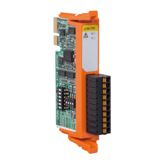
— — Product Nomenclature and Function CPSN-COM-1PD Reference Manual (Hardware) 1. Nomenclature of Product Components Component names of the product are shown in the figure below. Name Function LED Indicator This indicates status of the product. Interface Connector It is a connector for RS-422A/485 communication. Use the 10-pin connector included in the package. -
Page 17: Description Of Product Components
— — Product Nomenclature and Function CPSN-COM-1PD Reference Manual (Hardware) 2. Description of Product Components Components such as connectors, switches are described. 1. LED Indicator Status of the product is indicated by ON/OFF and flashing of LED. The meaning of each LED is described below. Color and Description Color Display... -
Page 18: Interface Connector
— — Product Nomenclature and Function CPSN-COM-1PD Reference Manual (Hardware) 2. Interface Connector This Product has 1 channel of RS-422A/485 communication. Use the 10-pin connector included in the package. Connector type: DEGSON 15EDGKC-3.81-10P-13 (or equivalent) Pin Assignment Pin No. Signal Name Description Signal ground RxD +... -
Page 19: Dip Switch
— — Product Nomenclature and Function CPSN-COM-1PD Reference Manual (Hardware) 3. DIP Switch DIP switch for RS-422A/485 setup. This Product has SW1 and SW2. SW1 is a switch used for data transmission mode. It is used to switch between full duplex and half duplex as well as to switch RTS and CTS in the full duplex. - Page 20 — — Product Nomenclature and Function CPSN-COM-1PD Reference Manual (Hardware) Setting Transmission Mode The data transmission mode setting switch is used to switch between full duplex and half duplex. Set the appropriate data transmitting mode for the device with which you are communicating. Bits 1.
- Page 21 — — Product Nomenclature and Function CPSN-COM-1PD Reference Manual (Hardware) Terminator Setup The terminator setting switch controls whether or not a terminator is inserted into each signal line. Set the terminators on or off in accordance with the devices with which you are communicating. The terminators on the board are 100Ω...
- Page 22 — — Product Nomenclature and Function CPSN-COM-1PD Reference Manual (Hardware) Full-duplex Self-loop RTS, CTS Connecting the RTS, CTS to the remote device — 22 —...
-
Page 23: Installation
Installation This section describes how to mount the product on a DIN rail or the wall, and to connect to an external device with a cable. — 23 —... -
Page 24: Install The Product
— — Installation CPSN-COM-1PD Reference Manual (Hardware) 1. Install the Product 1. Installation Conditions Installation Orientation You can position the CPU unit in the orientation shown below. Other orientations could cause problems such as malfunction due to inadequate heat dissipation. Vertical installation (Installation angle 0°) Vertical installation with an angle of 90°... - Page 25 — — Installation CPSN-COM-1PD Reference Manual (Hardware) Horizontal installation Make sure to gain proper space between the product and devices that generate heat or exhaust air so that the ambient temperature stays in the range specified in the environment requirement. Also, the temperature range in the environment requirements varies depending on the installation orientation, so check the operating temperature range in "Specifications(Page 34)".
- Page 26 — — Installation CPSN-COM-1PD Reference Manual (Hardware) CAUTION The product is an open-type device (a device designed to be housed inside other equipment) and must always be mounted inside a mechanical enclosure having enough strength. Note that although the ambient temperature is within the specified range, an operational ...
-
Page 27: Installation And Removal Of I/O Module And Blank Panels
— — Installation CPSN-COM-1PD Reference Manual (Hardware) 2. Installation and Removal of I/O Module and Blank Panels CAUTION Always confirm the PWR-LED of the CPU unit is turned off before installing or removing the module. Installation procedure Paying attention to the horizontal orientation of the I/O module, insert the resin groove into the rail of the CPU unit that has been installed on a DIN rail or that has been screwed into place, and then push the I/O module in until it clicks. - Page 28 — — Installation CPSN-COM-1PD Reference Manual (Hardware) Removal procedure Press in the hooks at the top and bottom of the I/O module, and then pull it toward you and out of the CPU unit that has been installed on a DIN rail or screwed into place. —...
-
Page 29: Connecting To An External Device
— — Installation CPSN-COM-1PD Reference Manual (Hardware) 2. Connecting to an External Device When connecting the product to an external device, use the supplied connector. When wiring the connector, strip off 8 mm ± 0.5 mm of the wires covering, and then insert this stripped part into the connectors opening. -
Page 30: Cable Connection
— — Installation CPSN-COM-1PD Reference Manual (Hardware) 3. Cable Connection 1. RS-422A/485 RS-422A/485 Cable Use the RS-422A/485 cable described below. Cable Twisted pair cable with the shield Applicable wire AWG28 - 16 (0.08mm - 1.25mm Cable Length Affected by the communication speed (baud rate) between the product and the external device. - Page 31 — — Installation CPSN-COM-1PD Reference Manual (Hardware) Maximum communication distances of the terminator resistor value (120Ω) and cable diameter Terminator Resistor (Ω) Cable Diameter Maximum Communication Distance (m) AWG28 AWG26 AWG24 1,200 AWG22 1,200 Setting the Baud Rate The baud rate range that can be set on this hardware is from 4 to 921,600 bps.
- Page 32 — — Installation CPSN-COM-1PD Reference Manual (Hardware) Types of Cable and Example Connections The figures below show examples of how to connect the cable for the board. The RS-422A/485 interface works based on a differential signal whereby the signal is carried by the potential difference between two lines (+ and -).
-
Page 33: Appendix
Appendix This section lists the specifications and the physical dimensions of the product, and the details of model name. — 33 —... -
Page 34: Specifications
— — Appendix CPSN-COM-1PD Reference Manual (Hardware) 1. Specifications Function Specifications Item CPSN-COM-1PD Number of channels Transmission scheme Asynchronous Serial Transmission (Full Duplex/Half Duplex) Interface type RS-422A/485 Isolation Bus Isolation Voltage Resistance 500VAC Baud Rate The setting range differs by the software program. See the reference manual (Software) for details.*1*2 *3 Data length Parity check... - Page 35 — — Appendix CPSN-COM-1PD Reference Manual (Hardware) Installation Environment Requirements Item CPSN-COM-1PD Operating ambient temperature*1 -20 - +60°C (Wall installation) -20°C to +55°C with a vertical installation at an angle of 90° to the left/right or with a plane installation Operating ambient humidity 10 - 90%RH (No condensation) Non-operating ambient...
-
Page 36: Physical Dimensions
— — Appendix CPSN-COM-1PD Reference Manual (Hardware) 2. Physical Dimensions Physical dimensions of CPSN-COM-1PD Physical dimensions of CPSN-COM-1PD (with connector attached) — 36 —... -
Page 37: The Details Of Model Name
— — Appendix CPSN-COM-1PD Reference Manual (Hardware) 3. The Details of Model Name Details of the model name are described below. Item Description Interface COM Serial Communication Channel 1 Channels Isolation Isolation Type Communication Type RS-422A/RS-485 — 37 —... -
Page 38: Optional Products
Optional Products This section lists optional items that can be used along with the product. — 38 —... -
Page 39: Optional Products
Remote I/O CPU unit LAN 2-channel model CPSN-MCB271-1-041 CODESYS Modbus Master CPU unit CPSN-PCB271-S1-041 DIN rail fitting power CPS-PWD-30AW24-01 Fitting power supply 30W supply (Input: 100 - 240VAC, Output: 24VDC 1.3 A) Visit the Contec website for the latest optional products. https://www.contec.com/ Website — 39 —... -
Page 40: Customer Support And Inquiry
Customer Support and Inquiry CONTEC provides the following support services for you to use CONTEC products more efficiently and comfortably. — 40 —... -
Page 41: Services
— — Customer Support and Inquiry CPSN-COM-1PD Reference Manual (Hardware) 1. Services CONTEC offers the useful information including product manuals that can be downloaded through the CONTEC website. Download https://www.contec.com/download/ You can download updated driver software, firmware, and differential manuals in several languages. Membership registration (myCONTEC) is required to use the services. - Page 42 — — Revision History CPSN-COM-1PD Reference Manual (Hardware) Revision History MONTH YEAR Summary of Changes February 2018 The First Edition September 2018 Additional information was listed due to some parts change. August 2019 Modified images and changed the layout of the manual. —...
- Page 43 3-9-31, Himesato, Nishiyodogawa-ku, Osaka 555-0025, Japan https://www.contec.com/ No part of this document may be copied or reproduced in any form by any means without prior written consent of CONTEC CO., LTD. CPSN-COM-1PD Reference Manual (Hardware) NA06022 (LYVS163) 08212019_rev3 [02202018] August 2019 Edition...
Need help?
Do you have a question about the CONPROSYS nano CPSN-COM-1PD and is the answer not in the manual?
Questions and answers