Table of Contents
Advertisement
Quick Links
Reference Manual
(Hardware)
Digital Input Module 16ch, Built-in power supply
CPSN-DI-16BCL
CONTENTS
Introduction .................................................................. 4
Safety Precautions .................................................... 10
Product Nomenclature and Function ............... 16
Installation ................................................................... 23
Appendix ...................................................................... 39
Optional Products .................................................... 44
Customer Support and Inquiry ............................ 46
Index .............................................................................. 48
Advertisement
Table of Contents

Related Manuals for Contec CONPROSYS nano CPSN-DI-16BCL


Summary of Contents for Contec CONPROSYS nano CPSN-DI-16BCL
- Page 1 Reference Manual (Hardware) Digital Input Module 16ch, Built-in power supply CPSN-DI-16BCL CONTENTS Introduction ..............4 Safety Precautions ............ 10 Product Nomenclature and Function ....16 Installation ..............23 Appendix ..............39 Optional Products ............ 44 Customer Support and Inquiry ......46 Index ................
-
Page 2: Table Of Contents
Table of Contents Introduction ............... 4 1. Related Manuals ..............................5 2. Check the Firmware Version ..........................6 3. About the Product ..............................7 4. Features ..................................8 5. Product Configuration List ..........................9 Safety Precautions ............10 1. Safety Information ............................... 11 2. Handling Precautions ............................12 1. - Page 3 Table of Contents Optional Products ............44 1. Optional Products..............................45 Customer Support and Inquiry ........46 1. Services ..................................47 Index .................. 48 — 3 —...
-
Page 4: Introduction
Introduction This section provides necessary information of the product such as the outline, bundled items and manuals before actual use. — 4 —... -
Page 5: Related Manuals
Reference Manual for I/O Download from Read this when operating the This describes the hardware aspects Module (Hardware) the Contec I/O module with CPU Unit. such as functions and settings of the website (PDF) I/O module. CPU unit Reference... -
Page 6: Check The Firmware Version
Before start using the product, visit our website to check the firmware version and update to the latest one if necessary. Updating firmware to the latest version will resolve troubles and stabilize the operation. https://www.contec.com/download/ Download Refer to the "Reference Manual (Software)" for the details of the firmware updating. -
Page 7: About The Product
— — Introduction CPSN-DI-16BCL Reference Manual (Hardware) 3. About the Product This product is an expansion I/O module that adds an opto-coupler isolated input interface with a response speed of 200 μs or less to the CPU unit of the CONPROSYS nano series. The product is equipped with 16 inputs and 1 common that support current sink/source output, and the internal circuit power supply of 12V and the external circuit power supply of 12-24V can be switched with the switch. -
Page 8: Features
— — Introduction CPSN-DI-16BCL Reference Manual (Hardware) 4. Features Opto-coupler isolated input The product contains 16 channels of opto-coupler isolated input whose response speed is 200µsec or less. Also, current sink outputs and current source outputs are switchable with the switch. ... -
Page 9: Product Configuration List
— — Introduction CPSN-DI-16BCL Reference Manual (Hardware) 5. Product Configuration List The product consists of the items listed below. Check, with the following list, that your package is complete. If you discover damaged or missing items, contact your retailer. Product…1 Product Guide &... -
Page 10: Safety Precautions
Safety Precautions Understand the following definitions and precautions to use the product safely. Never fail to read them before using the product. — 10 —... -
Page 11: Safety Information
— — Safety Precautions CPSN-DI-16BCL Reference Manual (Hardware) 1. Safety Information This document provides safety information using the following symbols to prevent accidents resulting in injury or death and the destruction of equipment and resources. Understand the meanings of these labels to operate the equipment safely. DANGER DANGER indicates an imminently hazardous situation which, if not avoided, will result in death or serious injury. -
Page 12: Handling Precautions
— — Safety Precautions CPSN-DI-16BCL Reference Manual (Hardware) 2. Handling Precautions DANGER Do not use the product in locations exposed to a flammable or corrosive gas. It may cause explosion, fire, electrical shock, or malfunction. Do not allow the device to come into contact with foreign substances (metal particles, ... - Page 13 When removing connectors or cables, always unplug the power cables of the CPU unit first, and confirm the LEDs are turned off. Do not modify the product. CONTEC will bear no responsibility for any problems, etc., resulting from modifying the product.
- Page 14 When disposing of the product, follow the disposal procedures stipulated under the relevant laws and municipal ordinances. Regardless of the foregoing statements, CONTEC is not liable for any damages whatsoever (Including damages for loss of business profits) arising out of the use or inability to use this CONTEC product or the information contained herein.
-
Page 15: Fcc Part15 Subpart B Class A Notice
— — Safety Precautions CPSN-DI-16BCL Reference Manual (Hardware) 1. FCC PART15 Subpart B Class A Notice NOTE This device complies with Part 15 of the FCC Rules. Operation is subject to the following two conditions: (1) this device may not cause harmful interference, and (2) this device must accept any interference received, including interference that may cause undesired operation. -
Page 16: Product Nomenclature And Function
Product Nomenclature and Function This section describes product component names and their functions, pin assignment of each connector. — 16 —... -
Page 17: Nomenclature Of Product Components
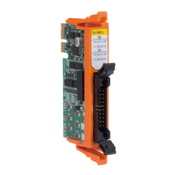
— — Product Nomenclature and Function CPSN-DI-16BCL Reference Manual (Hardware) 1. Nomenclature of Product Components Component names of the product are shown in the figure below. Name Function LED Indicator Displays the digital input status. Interface Connector This is a connector for digital input. Power Supply Switching Switch Use this switch to switch between the internal circuit power supply and the external circuit power supply. -
Page 18: Description Of Product Components
— — Product Nomenclature and Function CPSN-DI-16BCL Reference Manual (Hardware) 2. Description of Product Components Components such as connectors, switches are described. 1. LED Indicator When all the digital inputs are OFF, the LEDs all turn off. The hexadecimal value (0x0000) can be obtained with the software. -
Page 19: Digital Input Connector
— — Product Nomenclature and Function CPSN-DI-16BCL Reference Manual (Hardware) 2. Digital Input Connector This product has 16 channels of digital input. Connect with the 20-pin MIL connector. Connector used on the product: XG4A-2034 (OMRON) Compatible connector type: XG4M-2030 (OMRON) Pin Assignment Pin No. -
Page 20: Switching Switch
— — Product Nomenclature and Function CPSN-DI-16BCL Reference Manual (Hardware) 3. Switching Switch The product has switches to switch between internal and external circuit power supplies, and also between sink and source outputs. Switch Switch Description Use this switch to switch between the internal and external circuit power Power Supply Switching supplies. -
Page 21: Other Functions
— — Product Nomenclature and Function CPSN-DI-16BCL Reference Manual (Hardware) 3. Other Functions 1. Digital Filter You can use this function to apply a pulse filter to all the input terminals individually. This makes it possible to reduce the false recognition of input signals due to the noise and chattering that may be caused by switches and relays. -
Page 22: Interrupt Control Function
— — Product Nomenclature and Function CPSN-DI-16BCL Reference Manual (Hardware) 2. Interrupt Control Function Input signals of up to 16 input signals are usable as interrupt events. An interrupt is generated at the falling edge (HIGH-to-LOW transition) and the rising edge (LOW-to-HIGH transition), or at both of the edges. -
Page 23: Installation
Installation This section describes how to mount the product on a DIN rail, and to connect to an external device with a cable. — 23 —... -
Page 24: Install The Product
— — Installation CPSN-DI-16BCL Reference Manual (Hardware) 1. Install the Product 1. Installation Conditions Installation Orientation You can position the product in the orientation shown below. Other orientations may cause problems such as malfunctions due to inadequate heat dissipation. Vertical installation (Installation angle 0°) Vertical installation with an angle of 90°... - Page 25 — — Installation CPSN-DI-16BCL Reference Manual (Hardware) Horizontal installation Make sure to gain proper space between the product and devices that generate heat or exhaust air so that the ambient temperature stays in the range specified in the environment requirement. Also, the temperature range in the environment requirements varies depending on the installation orientation, so check the operating temperature range in "Specifications (Page 40)".
- Page 26 — — Installation CPSN-DI-16BCL Reference Manual (Hardware) Note that although the ambient temperature is within the specified range, an operational malfunction may occur if there is other device generating high heat; the radiation will influence the product to increase its temperature. Do not install this product into the fully-sealed space except the case in which the internal ...
-
Page 27: Installing And Removing I/O Module And Blank Panels
— — Installation CPSN-DI-16BCL Reference Manual (Hardware) 2. Installing and Removing I/O Module and Blank Panels CAUTION Always confirm the PWR-LED is turned off before installing or removing the module. Installing Paying attention to the horizontal orientation of the I/O module, insert the resin groove into the rail of the CPU unit that has been installed on a DIN rail or that has been screwed into place, and then push the I/O module in until it clicks. -
Page 28: Derating
— — Installation CPSN-DI-16BCL Reference Manual (Hardware) 2. Derating 1. Derating By the Number of Inputs The characteristic of derating by the number of inputs is shown in the following figure. Use this product within the derating range. Failing to do so may lead to malfunctions. ... - Page 29 — — Installation CPSN-DI-16BCL Reference Manual (Hardware) Derating by the number of inputs is unnecessary when using the internal circuit power supply (12V). When using more than one product, and derating by the number of inputs is necessary, use ...
-
Page 30: Connecting To An External Device
— — Installation CPSN-DI-16BCL Reference Manual (Hardware) 3. Connecting to an External Device When connecting the product to an external device, use the 20-pin MIL connector of this module. Connector used on the product: XG4A-2034 (OMRON) Compatible connector type: XG4M-2030 (OMRON) CAUTION Removing the connector plug by grasping the cable can break the wire. -
Page 31: Cable Connection
— — Installation CPSN-DI-16BCL Reference Manual (Hardware) 4. Cable Connection 1. Digital Input Digital input cable Use the digital input cable described below. Applicable wire AWG28 - 16 Cable Length Vary according to the environment where the product is used. *Refer to "Digital Input Connector"... - Page 32 — — Installation CPSN-DI-16BCL Reference Manual (Hardware) When removing the cable, open the locks outwardly and pull out the cable. — 32 —...
-
Page 33: Digital Input (Di)
— — Installation CPSN-DI-16BCL Reference Manual (Hardware) 2. Digital Input (DI) For the CPSN-DI-16BCL, opto-coupler-isolated input (supporting current sink/source output) is used for the digital input. The digital input is connected to a device that can perform current driving such as a switch or transistor output device. - Page 34 — — Installation CPSN-DI-16BCL Reference Manual (Hardware) Digital Input circuit (Internal circuit power supply, current sink output) Digital Input circuit (Internal circuit power supply, current source output) Digital Input circuit (Current sink output) (When the internal circuit power supply is used for operation check with LED) —...
- Page 35 — — Installation CPSN-DI-16BCL Reference Manual (Hardware) Digital input circuit (Current source output) (When the internal circuit power supply is used for operation check with LED) — 35 —...
- Page 36 — — Installation CPSN-DI-16BCL Reference Manual (Hardware) Example of connecting the product to a switch Example connection to the switch (External circuit power supply, current sink output) When the switch is “ON”, the relevant bit indicates “1”. When the switch is “OFF”, the relevant bit indicates “0”. Example connection to the switch (Internal circuit power supply, current source output) When the switch is “ON”, the relevant bit indicates “1”.
- Page 37 — — Installation CPSN-DI-16BCL Reference Manual (Hardware) Example connection to the switch (Internal circuit power supply, current source output) When the switch is “ON”, the relevant bit indicates “1”. When the switch is “OFF”, the relevant bit indicates “0”. — 37 —...
- Page 38 — — Installation CPSN-DI-16BCL Reference Manual (Hardware) Example of Connecting the Product to a Transistor Connection to the transistor (External circuit power supply, current sink output) Connection to the transistor (Internal circuit power supply, current source output) Connection to the transistor (Internal circuit power supply, current sink output) Connection to the transistor (Internal circuit power supply, current source output)
-
Page 39: Appendix
Appendix This section lists the specifications and the physical dimensions of the product, and the details of model name. — 39 —... -
Page 40: Specifications
— — Appendix CPSN-DI-16BCL Reference Manual (Hardware) 1. Specifications Function Specifications Item Description Input Input type Opto-coupler isolated input (supports current sink [negative logic] output *1/current source [positive logic] output *2) Isolation Opto-coupler Isolation Voltage Resistance 500VACrms Input Resistance 8.2kΩ Input ON current 1.0mA or more Input OFF current... - Page 41 — — Appendix CPSN-DI-16BCL Reference Manual (Hardware) Installation Environment Requirements Item Description Operating ambient temperature *1 -20 - +60°C (Vertical installation) -20°C to +55°C with a vertical installation at an angle of 90° to the left/right or with a horizontal installation. Operating ambient humidity 10 - 90%RH (No condensation) Non-operating ambient...
-
Page 42: Physical Dimensions
— — Appendix CPSN-DI-16BCL Reference Manual (Hardware) 2. Physical Dimensions — 42 —... -
Page 43: The Details Of Model Name
— — Appendix CPSN-DI-16BCL Reference Manual (Hardware) 3. The Details of Model Name Details of the model name are described below. Item Description Interface Digital Input Channel 16 Channel Model Type Built-in power supply Counter Communication Type 12 – 24VDC —... -
Page 44: Optional Products
Optional Products This section lists optional items that can be used along with the product. — 44 —... -
Page 45: Optional Products
Fitting power supply 30W supply (Input: 100 - 240VAC, Output: 24VDC 1.3 A) CPS-PWD-90AW24-01 Fitting power supply 90W (Input: 100 - 240VAC, Output: 24VDC 3.8 A) Visit the Contec website for the latest optional products. https://www.contec.com/ Website — 45 —... -
Page 46: Customer Support And Inquiry
Customer Support and Inquiry CONTEC provides the following support services for you to use CONTEC products more efficiently and comfortably. — 46 —... -
Page 47: Services
— — Customer Support and Inquiry CPSN-DI-16BCL Reference Manual (Hardware) 1. Services CONTEC offers the useful information including product manuals that can be downloaded through the CONTEC website. Download https://www.contec.com/download/ You can download updated driver software, firmware, and differential manuals in several languages. Membership registration (myCONTEC) is required to use the services. -
Page 48: Index
Index — 48 —... - Page 49 — — Index CPSN-DI-16BCL Reference Manual (Hardware) Revision History MONTH YEAR Summary of Changes August 2019 The First Edition — 49 —...
- Page 50 CONTEC CO., LTD. 3-9-31, Himesato, Nishiyodogawa-ku, Osaka 555-0025, Japan https://www.contec.com/ No part of this document may be copied or reproduced in any form by any means without prior written consent of CONTEC CO., LTD. CPSN-DI-16BCL Reference Manual (Hardware) NA06778 (LYXC242) 12132019_rev2 [08272019]...
Need help?
Do you have a question about the CONPROSYS nano CPSN-DI-16BCL and is the answer not in the manual?
Questions and answers