BYD Premium LVS 4.0 Service Manualline And Checklist
Battery-box
Hide thumbs
Also See for Premium LVS 4.0:
- Operating manual (47 pages) ,
- Service manuallines (13 pages)
Table of Contents
Advertisement
Quick Links
BYD Battery-Box Premium LVS
Service Guideline and Checklist
Version 1.1
Valid for Premium LVS 4.0 / 8.0 / 12.0 / 16.0 / 20.0 / 24.0
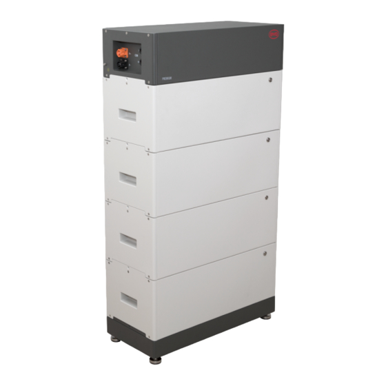
LVS 16.0 (4 Modules + PDU. Max. 64 Modules in 16 Towers per System)
Important: The installation and all other kinds of works or measurements in combination with the Battery-Box
Premium are only allowed by professional and qualified electricians.
This checklist is a shortened assistance for the Battery-Box and does not replace the original manual, which can
be found on
www.bydbatterybox.com
modifications; no responsibility is accepted for the accuracy of this information. Attention: Improper handling can
cause danger and damage.
Make sure to always use the latest version of this service document,
available at: www.bydbatterybox.com
/
www.eft-systems.de
/ www.alpspower.com.au. Subject to technical
BMU (1 x per System)
Advertisement
Table of Contents

Related Manuals for BYD Premium LVS 4.0


Summary of Contents for BYD Premium LVS 4.0
- Page 1 Service Guideline and Checklist Version 1.1 Valid for Premium LVS 4.0 / 8.0 / 12.0 / 16.0 / 20.0 / 24.0 LVS 16.0 (4 Modules + PDU. Max. 64 Modules in 16 Towers per System) BMU (1 x per System) Make sure to always use the latest version of this service document, available at: www.bydbatterybox.com...
-
Page 2: Table Of Contents
CONTENT CONTENT 1. GENERAL STEPS 2. ERROR ANALYSIS 2.1 BMU does not turn on / BMU LED is off or flickering abnormally 2.2 Modules do not show any reaction / No LED on module 2.3 Problem with the Firmware Update / App Configuration / Battery WiFi 2.4 Incorrect output voltage / No BMS Data / BMU EC102 2.5 Communication issue with Inverter / BMU EC106 2.6 SOC &... -
Page 3: General Steps
Notes about DC connection: - DC cable cross section: depends on the respective configuration. BYD does not specify a necessary cable cross-section herePlease pay attention to the power and current of the battery and the inverter, as well as the local rules. -
Page 4: Error Analysis
2. ERROR ANALYSIS Please refer to the general steps before proceeding, see chapter 1. 2.1 BMU does not turn on / BMU LED is off or flickering abnormally LEDs of BMU do not light up, although the battery is ON. Name Description Check correct cable port... -
Page 5: Problem With The Firmware Update / App Configuration / Battery Wifi
Only LED faulty? In some rare cases, the LED of the module is faulty. To check that: use PC Tool BCP and check under “diagnosis” if all modules (“BMS”) are detected correctly. Voltage measurement Check voltage of battery. See Section 2.10 Module Exclusion Method - Module Exclusion Method (see section 2.11): Check if the system works when removing the suspected module... -
Page 6: Incorrect Output Voltage / No Bms Data / Bmu Ec102
2.4 Incorrect output voltage / No BMS Data / BMU EC102 Wrong PDU output voltage (e.g 16V) is normally an indicator for incorrect configuration or BMU<>BMS communication issue Name Description Battery correctly Please check if the App configuration was successful and the Firmware is the configured? most recent one. -
Page 7: Communication Issue With Inverter / Bmu Ec106
Note: if PDU output voltage is incorrect (eg 16V) or BMS (cell) data cannot be seen in BCP, then go though section 2.4 first Name Description Configuration Check if the configuration is correct. Refer to latest “BYD Battery-Box Premium LVS Minimum Configuration List” (V1.7 or above) available at: www.bydbatterybox.com Make sure the inverter is configured and working correctly. -
Page 8: Bmu/Bms Led Event Code (Ec)
2.8 BMU/BMS LED Event Code (EC) A constant white LED refers to standby mode. White blinking means charge or discharge. When the battery is initiating, the LED will flash white and blue with an interval time of 0.5 seconds (normal during startup). When the LED flashes blue with an interval time of 1 second it indicates an event code. - Page 9 EC 102 Incorrect module quantity / Module not detected. EC 105 - See section 2.4. - Make sure the app-configuration has been completed correctly (especially module quantity!). - Check the terminal resistor. The terminal resistor (120 Ω at pin 5+6) is responsible for a clean communication between BMS and BMU.
-
Page 10: Be Connect Plus (Bcp)
2.9 Be Connect Plus (BCP) Be Connect Plus is a Windows-PC tool. With Be Connect Plus (BCP) you can: read the battery information, configure the battery system update BMU & BMS firmware Export / download battery logs (From BMU and all BMS) BCP is constantly being improved and updated. -
Page 11: Voltage Measurement And Undervoltage
2.10 Voltage measurement and undervoltage You can see the voltages (cells and module) in the app or BCP Tool (section 2.9). Alternatively you can measure the module voltage manually according to the description below. Make sure not to create a short circuit! To check the voltage on the PDU, the Modules have to be ON and the BMU has to be connected with the PDU! (LEDs on Modules and BMU have to be ON). -
Page 12: Module Exclusion Method (Identifying A Faulty Module)
Undervoltage A Module in which one of the 16 cells has a voltage of <1.5 V is in undervoltage (check with BCP (section 2.9) / BC if possible). - LVS Modules with >45 V should be fine and you can go on to check other points according to this service guideline. - If the module voltage is <40V but the single cell voltage is >1.5V, the battery needs to be charged quickly while avoiding any further discharge. -
Page 13: Service Tasks
3. SERVICE TASKS Please go through the general steps beforehand, see chapter 1. 3.1 BMU Replacement Have you detected a faulty BMU?: After replacing the BMU, please do not forget to re-do the configuration and firmware-update with the app or BCP. 3.2 PDU Replacement After replacing the PDU, please do not forget to re-do the configuration and firmware-update with the app or BCP. -
Page 14: Service Checklist And Contact Information
BYD Battery-Box Premium LVS Service Checklist - V1.1 EN Important: The installation and all other kinds of works or measurements in combination with the BYD Battery-Box are only allowed by professional and qualified electricians. Improper handling can cause danger and damage. This document does not replace the official BYD manuals and documents.
Need help?
Do you have a question about the Premium LVS 4.0 and is the answer not in the manual?
Questions and answers