BYD Premium LVS 4.0 Operating Manual
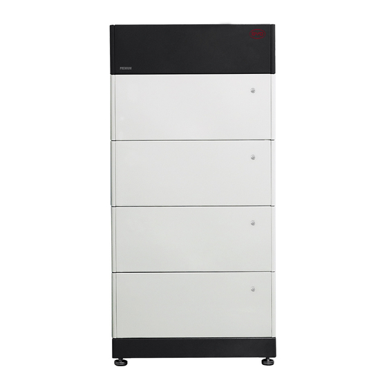
Battery box
Hide thumbs
Also See for Premium LVS 4.0:
- Service manuallines (13 pages) ,
- Service manualline and checklist (14 pages)

Related Manuals for BYD Premium LVS 4.0


Summary of Contents for BYD Premium LVS 4.0
- Page 1 BYD Battery-Box Premium Operating Manual LVS 4.0,8.0,12.0,16.0,20.0,24.0 V1.0 Download on the GET IT ON App Store Google play BYD Europe B.V. Be Connect...
-
Page 2: Legal Provisions
Legal Provisions All the information in this document is the property of BYD Europe B.V. No part of this document could be reproduced in any way for business use. Internal use is allowed. BYD Europe B.V. makes no representations or warranties express or implied, with respect to this document or any of the equipment and/or software it may describe, including (with no limitation) any implied warranties of utility, merchantability, or fitness for any particular purpose. -
Page 3: Table Of Contents
Content Legal Provisions ..........................1 Information on this Document ....................4 1.1. Validity ..........................4 1.2. Target Group ........................4 1.3. Content and Structure of this Document ................4 1.4. Declaration of Conformity ....................4 1.5. Levels of Warning Messages ................... 4 1.6. - Page 4 6.1. Overview of the Connection Area ................... 19 6.2. Connection Diagram ...................... 19 6.2.1. One Tower ........................19 6.2.2. Multiple Towers ......................20 6.3. Connecting the PE ......................20 6.4. Data Cable Connection ....................21 6.4.1. Data Cable Connection between Inverter and BMU ..........21 6.4.2.
-
Page 5: Information On This Document
1. Information on this Document 1.1. Validity This document is valid for the Battery-Box Premium LVS 4.0, 8.0, 12.0, 16.0, 20.0, 24.0. 1.2. Target Group The instructions in this document may only be performed by qualified persons who must have the following skills: •... -
Page 6: Symbols In The Document
1.7. Designation in the Document Designation in this document Complete designation Battery System Battery-Box Premium LVS Battery Information Collector Battery Management System Battery-Box Premium LV BMU(Battery Management Unit )-IP55 BYD Europe B.V. Power Distribute Unit State of Charge... -
Page 7: Safety
The battery system is suitable for indoor and outdoor use under the conditions mentioned in Section 5.1. The battery system must only be operated in connection with a compatible inverter. The list (BYD Battery-Box Premium LVS Minimum Configuration List) of these inverters could be found at www.bydbatterybox.com. -
Page 8: Battery Modules Handling And Storage Guide
2.2.3. Battery Modules Handling and Storage Guide • The battery modules and its components should be protected from damage when transporting and handling. • Do not impact, pull, drag, or step on the battery modules. • Do not insert unrelated objects into any part of the battery modules. •... -
Page 9: Caution Of Weight
Only open the PDU if the humidity is within the thresholds and the environment is free of • sand and dust. NOTICE Damage to the battery system due to under voltages If the battery system doesn't start at all, please contact BYD local after-sales service • within 48 hours. Otherwise, the battery could be permanently damaged. -
Page 10: Scope Of Delivery
3. Scope of Delivery PDU(For Australia Market) Base M4 Screw Hanger (PDU Part) Hanger (Wall Part) M5 Screw M6 Bolt and Nut Documents Communication Gland Metal Terminal O-Ring Claw DC Connector Rubber Core Battery Module M4 Screw PDU for Australia Market Battery module M4 Screw Hanger (PDU part) - Page 11 Metal Terminal Rubber Core O-ring Claw Battery Module...
-
Page 12: Battery System Overview
4. Battery System Overview 4.1. Battery System Description The Battery-Box Premium LVS is used as a connected battery for the intermediate storage of excess PV energy in an inverter system. It works together with Battery-Box Premium LV BMU-IP55 (BMU). The parameters and instruction of BMU could be read on our websites. -
Page 13: Interface
BMU is equipped with an Ethernet interface as a standard. When your battery system accesses the Internet, it will join our Be Connect Monitoring, which is a platform for BYD to provide remote service to customers. It can diagnose your battery system, and update the firmware. It is highly recommended you to access your system to the Internet. - Page 14 WEEE designation Do not dispose of the system together with the household waste but in accordance with the disposal regulations for electronic waste applicable at the installation site. CE marking The system complies with the requirements of the applicable EU directives.
-
Page 15: Led Signals
4.4. LED Signals 0.5S Flashing white and White The battery system is 0.5S blue alternatively initiating. Blue Idle (the battery system is neither White Glowing white charging nor Blue discharging). White The battery system is Flashing white slowly charging. Blue White The battery system is Flashing white quickly... -
Page 16: Installation
5. Installation 5.1. Requirements for Installation 5.1.1. Requirements for Installation Location a) A solid support surface must be available (e.g., concrete or masonry). b) The installation location must be inaccessible to children. The installation location must be suitable for the weight and dimensions of the battery system. d) The installation location must not be exposed to direct solar irradiation. -
Page 17: Additionally Required Installation Material
5.1.4. Additionally Required Installation Material RJ45 DC Cable(35mm /50mm /70mm ) Expansion Anchor Bolt(M8x40) PE with Terminal(SC16-5) Cat5 Shield 5.2. Installation CAUTION Risk of injury due to weight of the battery module Injuries may result if the battery module is lifted incorrectly or dropped while being transported or installed. - Page 18 Take a battery module from the package out. Put one battery module on the base. Pay attention to the direction of the module to make sure that the 45kg blind-mating connectors of the module and the base are at the same side. Repeat the operations for other battery modules.
- Page 19 13. Fix the two hangers (wall part and PDU part) with M6X16 bolts and nuts, using a cylinder screwdriver (10 mm) to tighten it (torque: 8 Nm). 14. Mark the product type.
-
Page 20: Electrical Connection
6. Electrical Connection 6.1. Overview of the Connection Area Gland for data cable in Gland for data cable out/terminal resistor Grounding point Gland for DC+ (P+) Gland for DC- (P-) 6.2. Connection Diagram 6.2.1. One Tower INVERTER INVERER ETHERNET The connection to Ethernet cable is recommended, not compulsory. -
Page 21: Multiple Towers
6.2.2. Multiple Towers INVERTER INVERER ETHERNET 6.3. Connecting the PE Additionally required mounting material (not included in the scope of delivery): Additionally required mounting material (not included in the scope of delivery): PE with Terminal (SC16-5) PE and Terminal Requirement a) Terminal SC16-5 b) Minimum terminal cross-section: 10 mm²... -
Page 22: Data Cable Connection
The cross-section of the grounding terminal must comply with the locally applicable standards and directives d) PE cross-section: 16 mm² e) PE Material: Copper wire Procedure: Make sure the PDU air switch is off. (This step is only applicable for the Australia market). Take out the grounding screw, and get the PE conductor through it. - Page 23 Assignment 485-A 485-B Unused CAN H CAN L Unused Unused Unused Our compatible inverters’ communication ports with BMU designation could be read below. STUDER VICTRON SELECTRONIC SOLAREDGE GOODWE The detailed connection instruction with different inverters could be read in the Appendix. Note: the information here is just for reference.
-
Page 24: Data Cable Connection Between Bmu And Pdu
Tighten the gland. Plug the RJ45 connector to the corresponding port at the inverter. 6.4.2. Data Cable Connection between BMU and PDU Additionally required mounting material (not included in the scope of delivery): One data cable Data cable requirements: The cable length and quality affect the quality of the signal. Observe the following cable requirements. -
Page 25: Cover The Terminal Resistor
• Shielding: Yes • UV-resistant for outdoor use • Straight- through wired cables • Maximum cable length: 10 m. Procedure: Plug the RJ45 connector to the Ethernet port of BMU. Refer to the procedure of Point 2 to 4 of Section 6.4.1 Plug the RJ45 connector at the other side of the cable to a router port. -
Page 26: Dc Connection
INVERER ETHERNET .. . Data cable requirements: The cable length and quality affect the quality of the signal. Observe the following cable requirements. Cable category: Cat5, Cat5e or higher • Plug type: Metal shielded RJ45 of Cat5, Cat5e or higher •... - Page 27 Additionally required mounting material (not included in the scope of delivery): Two DC power cables Cable requirements: Conductor cross-section: four options are available, 35mm, 50mm, 70mm and 95 mm. Please • choose the correct one according to application and also the requirements of the inverter manufacturer.
- Page 28 Install rubber core, O-Ring and cap in sequence on the DC cable. Strip the PE insulation sleeve up to 20 ± 1.0 mm 20 ± 1.0 mm Plug the DC terminal into the stripped part of the cable. Clamp the metal terminal with hydraulic clamper. Before that, please make sure the correct dies are chosen.
- Page 29 Plug the metal terminal into the connector. Plug the branches of the rubber core to the holes of O-ring. Push the integrated part rubber core and O-ring into the connector, and make sure that the O-ring is totally inside of the connector. Push the cap to make sure the cap and the connector clutched well.
- Page 30 10. Remove the protective covers on the connectors and the PDU. 11. Plug the cables into the PDU. The other side of the cables should be well protected if it is not installed at this step.
-
Page 31: Commissioning
7. Commissioning 7.1. Switch on the Battery System Requirements: The power cable connection between the battery system and the inverter is switched off. • The inverter must be correctly mounted. • All cables must be correctly connected. • Procedure: INVERTER ETHERNET INVERER (if available) -
Page 32: Configure The Battery System
4. Read the privacy policy and click the Confirm button to go to the Privacy Policy of next page. You can also download the full PDF document by SHEN ZHEN BYD clicking the Download button, which requires the Internet ELECTRONIC CO,.LTD available on your device. - Page 33 WLAN 6. Connect the WLAN of the battery system. AVAILABLE NETWORKS BYD-XXXX The name of the WLAN is printed on the BMU. Connected (no lnternet access) 4G-CPE-299430 Saved,encrypted All the WLAN shares the common password BYD-XXXX Saved,encrypted (BYDB-Box). Turning off the Cellular Data and...
- Page 34 10. Choose the battery system model, LVS. And then set how many battery modules are installed per tower. Time Inverter System Grid Model Confirm Back Configuration System Information Service Contact 11. Choose the Grid and Phase options according to the actual application.
-
Page 35: Switch On And Commission The Inverter
7.3. Switch on and Commission the Inverter Procedure: 1. Mount and connect the inverter according to the inverter manufacturer`s instruction. 2. Commission and configure the inverter according to the inverter manufacturer`s instruction. If the battery information could be read correctly, it means the connection between the battery system and the inverter is all right. -
Page 36: Operation
8. Operation 8.1. Switch on the Battery System To make sure the battery system can work well with the inverter, please follow the right procedure to start them. The procedure is: 1) turn on the switch between the inverter and battery if there is any; 2) switch on the battery system;... -
Page 37: Switch Off The Battery System
8.2. Switch off the Battery System The procedure to switch off the battery system is: 1) switch off the inverter; 2) switch off the battery; 3) switch off the air switch between the battery and the inverter if there is any. The way to switch off the battery system is to press the LED Button on the BMU for 5 seconds. -
Page 38: Maximum Current At Different Temperature
8.3. Maximum Current at Different Temperature Maximum charge Maximum discharge Temperature Remarks current current -10℃≤T<0℃ *N of the modules 0℃≤T<5℃ *N of the modules *N of the modules, up 5℃≤T<50℃ to 250A per tower 8.4. Protective Devices The battery system could protect itself (switch off) if the Battery-Box Premium LVS Minimum Configuration List is not complied. -
Page 39: Decommissioning
9. Decommissioning CAUTION Risk of injury due to weight of the battery module Injuries may result if the battery module is lifted incorrectly or dropped while being transported or installed. Transport and lift the battery module carefully. Take the weight of the battery module into •... -
Page 40: Extension
Extension The battery system could be extended at any time. The original SOC of the new battery module is around 30%. Procedure: Shut off the inverter. Switch off the battery system. Switch off the breaker between the inverter and the battery system if there is any. Take the PDU off. -
Page 41: Troubleshooting
The battery system is not able to be turned on. Check the system has been constructed according to the Battery-Box Premium Compatible Inverter List. If the problem still cannot be solved, contact with BYD local after-sales service within 48 hours. NOTICE... - Page 42 Blue LED is flashing eleven times BMS and BMU communication failure Blue LED is flashing twelve times Inverter communication failure Blue LED is flashing thirteen times Address registration failed Blue LED is flashing fourteen times System parameters loading failed...
-
Page 43: Maintenance And Storage
Maintenance and Storage Cleaning It is recommended that the battery system be cleaned periodically. If the enclosure is dirty, please use a soft, dry brush or a dust collector to remove the dust. Liquids such as solvents, abrasives, or corrosive liquids should not be used to clean the enclosure. Maintenance The battery module should be stored in an environment with a temperature range between -10°C~... -
Page 44: Disposal Of The Battery System
• Do not dispose of the battery system with your household waste. • Avoid exposing the batteries to high temperatures or direct sunlight. • Avoid exposing the batteries to high humidity or corrosive atmospheres. • For more information, please contact BYD. -
Page 45: Technical Parameters
Warranty [4] 10 Years Compatible Inverters Refer to BYD Battery-Box Premium LVS Minimum Configuration List Battery designation IFpP/47/174/120/16S/M/-10+50/90 [1] DC Usable Energy, Test conditions: 100% DOD, 0.2C charge & discharge at + 25 ° C. System Usable Energy may vary with different inverter brands [2] Charge derating will occur between -10 °... -
Page 46: Contact Information
Contact Information BYD Global Service bboxservice@byd.com Social media link Telephone: +86 755 89888888-47175 https://www.facebook.com/BatteryBoxBYD/ Address:No.3009,BYD Road, https://twitter.com/BYD_BatteryBox Pingshan,Shenzhen,518118,P.R.China https://www.linkedin.com/company/byd-battery-box www.bydbatterybox.com Australia Alps Power Pty Ltd Europe EFT-Systems GmbH service @alpspower.com.au service@eft-systems.de Telephone: +61 2 8005 6688 Telephone +49 9352 8523999... -
Page 47: Appendix Data Cable Connection Instruction With Inverters
Appendix Data Cable Connection Instruction with Inverters Connection with SMA Connection with SOLAREDGE SOLAREDGE PIN6 PIN2 Connection with SELECTRONIC Connection with VICTRON SELECTRONIC VICTRON Connection with GOODWE Connection with STUDER GOODWE STUDER...
Need help?
Do you have a question about the Premium LVS 4.0 and is the answer not in the manual?
Questions and answers