Table of Contents
Advertisement
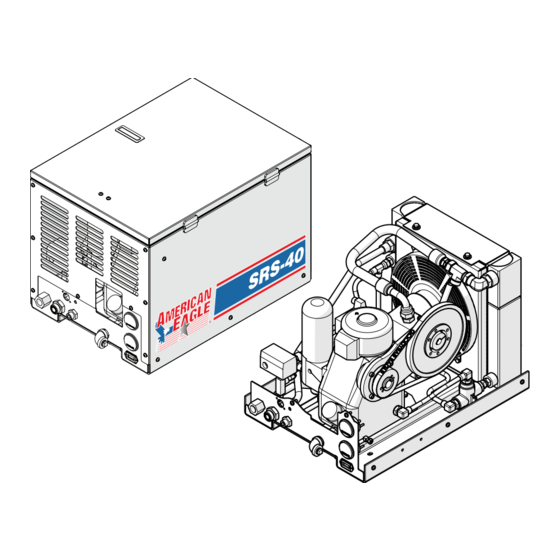
Models
SRS-40RP (PN 53886)
SRS-40E (PN 54373)
SRS-40P (PN 53888)
Subject to Change without Notification.
© 2011 American Eagle, Inc.
Safety • operation • Installation • Parts
American Eagle, Inc.
740 N. State Street
PO Box 169
Garner, IA 50438
800-392-3015
Fax: 641-923-9099
www.americaneagleacc.com
M
odEl
R
S
otaRy
cREw
o
wNERS
SRS-40
c
oMPRESSoR
' M
aNual
Last Revision: 07/22/11
Advertisement
Table of Contents

Subscribe to Our Youtube Channel
Related Manuals for American Eagle SRS-40


Summary of Contents for American Eagle SRS-40
- Page 1 Models SRS-40RP (PN 53886) SRS-40E (PN 54373) SRS-40P (PN 53888) American Eagle, Inc. 740 N. State Street PO Box 169 Garner, IA 50438 800-392-3015 Fax: 641-923-9099 Subject to Change without Notification. www.americaneagleacc.com © 2011 American Eagle, Inc. Last Revision: 07/22/11...
- Page 2 SRS-40 Manual Revisions...
-
Page 3: Table Of Contents
Table of Contents Table of Contents Introduction ..............ii Chapter 1 - Safety . -
Page 4: Introduction
This manual is not binding. American Eagle, To promote this longevity, carefully study the Inc. reserves the right to change, at any information contained in this manual before time, any or all of the items, components, putting the equipment into service. -
Page 5: Chapter 1 - Safety
Do not operate the compressor unless thor- Please take note that American Eagle, Inc. is oughly trained or under the supervision of an not liable for accidents incurred by the instructor. -
Page 6: Safety Decals (From Kit Pn 22418)
SRS-40 Owner’s Manual Safety Decals (From Kit PN 22418) WARNING WARNING WARNING WARNING Do not remove caps, High pressure All hoses should be Hot parts can plugs, or other hydraulic system. connected in full cause severe components while compliance with burns. -
Page 7: Chapter 2 - Specifications
Specifications Chapter 2 - Specifications SPECIFICATIONS SRS-40RP SRS-40E SRS-40P Hydraulic System 19-20 12 GPM 12 GPM Compressor RPM 7500-8000 RPM 7500-8000 RPM 7500-8000 RPM System Pressure 2000 PSI 2800 PSI 2800 PSI Max Air Pressure 150 PSI 175 PSI Relief 2500 PSI 2500 3500 PSI... - Page 8 SRS-40 Owner’s Manual...
-
Page 9: Chapter 3 - Operation
Check the oil level in the compressor (See Section “Changing the Oil”). If oil is needed, use American Eagle synthetic compressor oil (P/N C0087) or an equivalent synthetic oil. Check hoses (air and hydraulic) for weak or worn condition and make sure that all con- nections are secure. - Page 10 SRS-40 Owner’s Manual Air Operations (SRS-40P) Operating Notes: Activating the compressor switch sends This rotary screw compressor must not be power to the cooling fan and normally used for breathing air. To do so will cause closed terminal (87A) of the Bosch relay.
-
Page 11: Chapter 4 - Maintenance
The following table is a list of routine maintenance items, including service intervals. Service intervals are listed as hours, days, or weeks, whichever occurs first. American Eagle recom- mends that these service intervals be followed. Before performing any maintenance func- tion, turn off compressor, hydraulic system, truck engine and remove keys to assure that compressor is not started. -
Page 12: Oil Level
SRS-40 Owner’s Manual Oil Level The oil level in the compressor case is an important factor for the operational reliability of the system. Check Intervals: 1. Before starting unit. 2. Every 100 operating hours Check Procedures: 1. Turn off the compressor, hydraulic system and truck engine to ensure that compressor is not start- 2. -
Page 13: Changing The Oil
Maintenance Changing the Oil WARNING: COMPRESSOR MUST BE STOPPED AND ALL AIR RECEIVERS DISCHARGED BEFORE CHANGING OIL. COMPRESSOR OIL IS HOT, ABOVE 175 DEGREES F (80 DEGREES C) AND CAN CAUSE BURNS. Note: Change the oil with the compressor at operating temperature of 140-175 degrees F (60-80 degrees C). -
Page 14: Oil Filter
SRS-40 Owner’s Manual Oil Filter The oil filter is located to the front of the unit. When viewing the unit from the oil fill cap end, the oil filter will be to the left front. It is necessary to remove the side panel to access the oil filter. Replace the filter after the first 50 hours of service and every 1,000 hours thereafter. -
Page 15: Belt Tension
Maintenance Belt Tension Belt Deflection NEW BELT Installation Tension: 98.0 lbf Tensioning Force: 6.8 lbf Force Applied Belt Deflection: 9/64 in Span Length: 9.00 in USED BELT Installation Tension: 65.4 lbf Tensioning Force: 4.8 lbf Belt Deflection: 9/64 in Span Length: 9.00 in Span Minimum Pressure Valve The minimum pressure valve is set at the factory. -
Page 16: Hydraulic Oil Cooler/Compressor Oil Cooler
SRS-40 Owner’s Manual Hydraulic Oil Cooler/Compressor Oil Cooler For reliable operation and longevity of both compressor and hydraulic system, the cooler should be kept clean. The compressor system is protected from operation at high temper- ature by a switch gauge. If the compressor shuts down or is operating close to the shut down temperature, the cooler should be cleaned. -
Page 17: Chapter 5 - Installation
Installation Chapter 5 - Installation Component Installation Notice: Read this Page Before Installation of the Compressor This section pertains to the installation of the Electrical Connections: air compressor, PTO, pump and other relat- From the air pressure switch there are two ed items. -
Page 18: Electrical Installation
SRS-40 Owner’s Manual Electrical Installation RED WIRE (NOT USED) RED WIRE (NOT USED) BLACK WIRE... -
Page 19: Temperature Gauge Installation
Installation Temperature Gauge Installation USE THIS PORT FOR THE TEMP GAUGE PROBE DO NOT ATTEMPT TO INSTALL TEMPERATURE GAUGE INTO THIS PORT. DAMAGE WILL RESULT! -
Page 20: Hydraulic System
A 3/4” minimum low-pressure return line is connected to the oil cooler outlet and is routed to the oil reservoir. American Eagle recommends a sufficient sized reservoir be provided that includes the proper suction and return filters. The cooler on the compressor is designed and sized to cool the air compressor efficiently. -
Page 21: Compressor Pressure Switch
Installation Compressor Pressure Switch (RP/E Models Only) Kick Out (Step 1) Pressure Setting Adjustment Screw (145-150 psi) Kick On (Step 2) Pressure Setting Adjustment Screw (115-120 psi) Note: Turning adjustment screws clockwise increases psi settings. Turning adjustment screws counterclockwise decreased psi settings. Location inside box of SRS Compressors Pressure Setting Instructions: 1. -
Page 22: Typical Hydraulic Circuit For Single Stage Pump
SRS-40 Owner’s Manual Typical Hydraulic Circuit for Single Stage Pump PN 30532 Typical Hydraulic Circuit for Tandum (Two Part) Pump... -
Page 23: Typical Hydraulic Circuit For Compressor With Auxiliary Cooler
Installation Typical Hydraulic Circuit for Compressor with Auxiliary Cooler HYDRAULIC RESERVOIR FILTER FILTER SCREEN AUXILIARY COOLER SUCTION PORT SINGLE HYDRAULIC PUMP COMPRESSOR RETURN PRESSURE... - Page 24 SRS-40 Owner’s Manual...
-
Page 25: Chapter 6 - Assembly Drawings
Assembly Drawings Chapter 6 - Assembly Drawings SRS-40RP Compressor Assembly PN 53886 Pages 22-23 SRS-40E Compressor Assembly PN 53888 Pages 24-25 SRS-40P Compressor Assembly PN 54373 Pages 26-27... -
Page 26: Srs-40Rp Compressor Assembly - Pn 53886
SRS-40 Owner’s Manual SRS-40RP Compressor Assembly - PN 53886 25 24... -
Page 27: Srs-40E Compressor Assembly - Pn 53888
Assembly Drawings SRS-40RP Compressor Assembly - PN 53886 ITEM PART DESCRIPTION QTY. ITEM PART DESCRIPTION QTY. 11403PC BASE WELDMT NK40 12856 CAP 0.50 PIPE HEX 5406-8 19540 CPRSR SRS40 NK40 ROTORCOMP 12122 BOLT 0.38X1.00 EYE 567-23-ZN 21417 BRKT MOTOR MOUNT SRS40 22162 CAP SCR 8MMX25MM SHCS 22019... -
Page 28: Srs-40P Compressor Assembly - Pn 54373
SRS-40 Owner’s Manual SRS-40E Compressor Assembly - PN 54373 25 24... - Page 29 Assembly Drawings SRS-40E Compressor Assembly - PN 54373 ITEM PART DESCRIPTION QTY. ITEM PART DESCRIPTION QTY. 11403PC BASE WELDMT NK40 12856 CAP 0.50 PIPE HEX 5406-8 19540 CPRSR SRS40 NK40 ROTORCOMP 12122 BOLT 0.38X1.00 EYE 567-23-ZN 21417 BRKT MOTOR MOUNT SRS40 22162 CAP SCR 8MMX25MM SHCS MOTOR HYD 20.14S0-49S1-LOC/OD-N-EL-...
- Page 30 SRS-40 Owner’s Manual SRS-40P Compressor Assembly - PN 53888 25 24...
- Page 31 Assembly Drawings SRS-40P Compressor Assembly - PN 53888 12856 CAP 0.50 PIPE HEX 5406-8 12122 BOLT 0.38X1.00 EYE 567-23-ZN 21417 BRKT MOTOR MOUNT SRS40 22162 CAP SCR 8MMX25MM SHCS MOTOR HYD 20.14S0-49S1-LOC/OD-N-EL- C6245 FTG ADAPT TUBE-MNPT 90 1/4-1/8 BRASS 51226 21298 FTG ADAPT MBSPP/FNPT 1/4-1/4 F4OHG 21300...
- Page 32 SRS-40 Owner’s Manual...
-
Page 33: Chapter 7 - Replacement Parts
Replacement Parts Chapter 7 - Replacement Parts HYDRAULIC COMPONENTS/DRIVE PARTS PART# DESCRIPTION C4914 Relief Valve (RP/E Models Only) 51234 Relief Valve (P Model Only) C4499 Solenoid Valve 3858 Solenoid Valve 24 Volt 22019 Hydraulic Motor (RP/E Models Only) 51226 Hydraulic Motor (P Model Only) 21652 Sprocket (Hyd Motor) 21653... - Page 34 SRS-40 Owner’s Manual...
-
Page 35: Chapter 8 - Troubleshooting
Troubleshooting Chapter 8 - Troubleshooting If symptoms of poor performance develop, the following chart can be used as a guide to investigate and correct the problem. When diagnosing faults in operations of the air compressor, always check that the hydraulic power source is supplying the correct hydraulic flow and pressure that is listed in the compressor specification section of this manual. -
Page 36: Warranty Information
Warranty service will be performed by any American Eagle new equipment distributor, or by any American Eagle-recognized service center authorized to service the type of product involved, or by the American Eagle factory in the event of a direct sale. At the time of requesting warranty service, the owner must present evidence of date of delivery of the product.
Need help?
Do you have a question about the SRS-40 and is the answer not in the manual?
Questions and answers