Soundoff Signal P Series Manual
Warning light
Hide thumbs
Also See for P Series:
- Instruction manual (10 pages) ,
- Manual (10 pages) ,
- Quick start manual (9 pages)
Advertisement
Quick Links
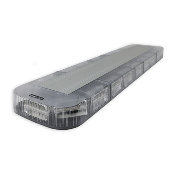
P SERIES 7X3 - WARNING LIGHT
EPSSC0JX(x)-(x) - STUD MOUNT
EPSSC0JY(x)-(x) - SCREW MOUNT
WARNING
•HIGH CURRENT interconnects must be properly terminated. Poor crimp quality can cause heat build-up and fire. Follow crimp
connector manufacturer instructions.
•DO NOT install this product or route any wires in the Air Bag Deployment Zone. Refer to vehicle Owner's Manual for deployment zones.
•Unit may become hot to touch during normal operation.
•Failure to properly install connectors, fuses or wiring may cause vehicle failure or fire.
•Installation must only be performed by trained technician. Installer must determine vehicle wiring configuration and proper integration of
system.
•Use proper wire gauge. All power wires connecting to positive (+) or negative (-) battery terminal or local chassis ground (-) must be
sized to supply at least 125% of max. current and properly fused at power source.
•Install protective grommets when routing wire through firewall or metal.
1.800.338.7337 / www.soundoffsignal.com
1
Installers and users must comply with all applicable federal, state and local laws regarding use and installation of warning devices.
To review our Limited Warranty Statement & Return Policy for this or any SoundOff Signal product, visit our website at www.soundoffsignal.com/tech-services/returns/.
If you have questions regarding this product, contact Technical Services, Monday - Friday, 8 a.m. to 5 p.m. ET at 1.800.338.7337 (press #4).
Questions or comments that do not require immediate attention may be emailed to techservices@soundoffsignal.com.
NOTICE:
Improper use or installation may void warranty coverage.
E N H A N C I N G S A F E T Y T H R O U G H I N N O VAT I O N
P SERIES 7X3 WARNING LIGHT
TECHNICAL SPECIFICATIONS
Input Voltage:
WARNING LIGHT
CURRENT CONSUMPTION (Amps)
12.8Vdc
Peak
Average
Peak
Red
1.55
0.78
0.78
Amber, Blue,
Green or
1.90
0.95
0.95
White
AFTER POWER IS ON, touching the WHITE wire to the ground
will allow you to change various settings on the module. (refer to
page 7).
NOTE: It is recommended to use the Stud Mount
option for any dynamic mount surfaces (i.e.
Swinging Panels, Doors, and Tail Gates).
WARNING
!
This product contains high intensity LED devices.
To prevent eye damage, DO NOT stare into the
light beam at close range.
Protected by U.S. Patent 10,703,260 and Patents Pending
https://soundoffsignal.com/legal/patent-notification/
7X3 POLYCARB_WARNING 1121
9-32Vdc
25.6Vdc
Average
0.39
0.48
Advertisement

Related Manuals for Soundoff Signal P Series


Summary of Contents for Soundoff Signal P Series
- Page 1 Improper use or installation may void warranty coverage. To review our Limited Warranty Statement & Return Policy for this or any SoundOff Signal product, visit our website at www.soundoffsignal.com/tech-services/returns/. If you have questions regarding this product, contact Technical Services, Monday - Friday, 8 a.m. to 5 p.m. ET at 1.800.338.7337 (press #4).
- Page 2 FIG. 1 SCREW MOUNT INSTALLATION 1. Drill (4) 5/16 holes to mount light. Drill 3/4" wire hole. See Fig. 2 2. Insert well nuts into the 4 drilled holes. Fully seat to mounting surface. 3. Align the gasket to the mounting surface. WIRE HOLE NOTE: Horizontal and vertical orientations indicated GASKET...
- Page 3 Improper use or installation may void warranty coverage. To review our Limited Warranty Statement & Return Policy for this or any SoundOff Signal product, visit our website at www.soundoffsignal.com/tech-services/returns/. If you have questions regarding this product, contact Technical Services, Monday - Friday, 8 a.m. to 5 p.m. ET at 1.800.338.7337 (press #4).
- Page 4 FIG. 1 STUD MOUNT INSTALLATION 1. Drill (2) 1/4" holes to mount light. Drill 3/4" wire hole. See Fig. 2 WIRE HARNESS 2. Thread studs into back of light. 3. Align gasket to mount surface. NOTE: Horizontal and vertical orientations indicated on gasket for proper seal.
-
Page 5: Flash Patterns
WIRING AND TABLE INFORMATION OVER-VOLTAGE PROTECTION When an over-voltage condition is detected, the module will flash an over-voltage warning pattern of 50mS ON/950mS OFF to alert of the over-voltage condition and protect the electronics from damage due to heat/ voltage. THERMAL COMPENSATION PROTECTION The LED module is designed to provide maximum power output while providing protection to the electronic components by reducing the output power at extreme temperatures. - Page 6 WIRING AND TABLE INFORMATION (CONT.) FUNCTION TABLES The functional operation of the LED module can be changed while applying the +V to the Red wire with the Black wire connected to ground. When the light is flashing, momentarily connect the White wire to ground for >4S and <5S (light will go steady high, steady low, off, steady high, steady low) then release.
- Page 7 WIRING AND TABLE INFORMATION (CONT.) REMOTE MODE: FOR USE WITH bluePRINT® SYSTEM ONLY Connecting the Green wire to ground before applying power to the Red wires will place the LED module into remote mode and the light output color will be directly controlled by the input wires as shown below. For Cruise mode or Low Power control of the LED module, the signal to the control wires must be 100 +/- 2Hz using the duty cycle inputs listed below to produce the light output.
- Page 8 WIRING AND TABLE INFORMATION (CONT.) SIMULTANEOUS/ALTERNATE This function can only be changed when the LED module is in a flashing mode (disabled in cruise or steady ON functions) and only has an effect when at least 2 LED modules have the green sync wire connected together.
- Page 9 Improper use or installation may void warranty coverage. To review our Limited Warranty Statement & Return Policy for this or any SoundOff Signal product, visit our website at www.soundoffsignal.com/tech-services/returns/. If you have questions regarding this product, contact Technical Services, Monday - Friday, 8 a.m. to 5 p.m. ET at 1.800.338.7337 (press #4).
Need help?
Do you have a question about the P Series and is the answer not in the manual?
Questions and answers