Advertisement
Quick Links
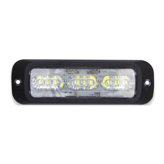
BOLT2 LED LIGHT
E1XS2SME5(xx)
Please see last page for Technical Specifications
WARNING
•HIGH CURRENT interconnects must be properly terminated. Poor crimp quality can cause heat
build-up and fire. Follow crimp connector manufacturer instructions.
•DO NOT install this product or route any wires in the Air Bag Deployment Zone. Refer to vehicle
Owner's Manual for deployment zones.
•Unit may become hot to touch during normal operation.
•Failure to properly install connectors, fuses or wiring may cause vehicle failure or fire.
•Installation must only be performed by trained technician. Installer must determine vehicle wiring
configuration and proper integration of system.
•Use proper wire gauge. All power wires connecting to positive (+) or negative (-) battery terminal
or local chassis ground (-) must be sized to supply at least 125% of max. current and properly fused at
power source.
•Install protective grommets when routing wire through firewall or metal.
1.800.338.7337 / www.soundoffsignal.com
Pg. 1
Installers and users must comply with all applicable federal, state and local laws regarding use and installation of warning devices.
To review our Limited Warranty Statement & Return Policy for this or any SoundOff Signal product, visit our website at www.soundoffsignal.com/tech-services/returns/.
If you have questions regarding this product, contact Technical Services, Monday - Friday, 8 a.m. to 5 p.m. or after hours 5 p.m. to 8 p.m. ET at 1.800.338.7337 (press #4).
Questions or comments that do not require immediate attention may be emailed to techservices@soundoffsignal.com.
S U P E R I O R C U S TO M E R R E L AT I O N S H I P S . S M A RT LY D E S I G N E D L I G H T I N G & E L E C T R O N I C S O L U T I O N S .
NOTICE:
Improper use or installation may void warranty coverage.
INSTALLATION
1. Establish a position on the vehicle on a level
surface. Orient the light output level on the
horizon.
2. Use the screw holes in the assembly as a
template to mark locations of wire and
mounting screws.
3. Use a 3/4" (19MM) diameter drill for the wire
holes.
4. Size pilot holes for mounting screws
appropriately.
5. Fasten light using mounting
screws. Do not torque mounting screws
beyond 10 in-lbs (1.13 N-m.)
WIRE HOOK-UP TABLE
WIRE COLOR:
CONNECT TO:
RED +10-30 Vdc (Color 1)
YELLOW +10-30 Vdc (Color 2)
BLACK
(-) Ground
Pattern Select +Vdc/
WHITE
Sync
GREEN (+) Dim/ Night Mode
WARNING
!
This product contains high intensity LED devices. To
prevent eye damage, DO NOT stare into the light
beam at close range.
E1XS2SME5xx 0219
Advertisement

Subscribe to Our Youtube Channel
Related Manuals for Soundoff Signal BOLT2


Summary of Contents for Soundoff Signal BOLT2
- Page 1 Improper use or installation may void warranty coverage. To review our Limited Warranty Statement & Return Policy for this or any SoundOff Signal product, visit our website at www.soundoffsignal.com/tech-services/returns/. If you have questions regarding this product, contact Technical Services, Monday - Friday, 8 a.m. to 5 p.m. or after hours 5 p.m. to 8 p.m. ET at 1.800.338.7337 (press #4).
- Page 2 Improper use or installation may void warranty coverage. To review our Limited Warranty Statement & Return Policy for this or any SoundOff Signal product, visit our website at www.soundoffsignal.com/tech-services/returns/. If you have questions regarding this product, contact Technical Services, Monday - Friday, 8 a.m. to 5 p.m. or after hours 5 p.m. to 8 p.m. ET at 1.800.338.7337 (press #4).
Need help?
Do you have a question about the BOLT2 and is the answer not in the manual?
Questions and answers