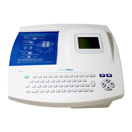
Welch Allyn CP 100 Service Manual
12-lead resting electrocardiograph
Hide thumbs
Also See for CP 100:
- Directions for use manual (90 pages) ,
- Update to directions for use (42 pages) ,
- Quick start manual (2 pages)

Related Manuals for Welch Allyn CP 100


Summary of Contents for Welch Allyn CP 100
- Page 1 CP 100 and CP 200™ 12-Lead Resting Electrocardiograph CP 200 12- Lead Resting Electrocardiograph CP 100 12- Lead Resting Electrocardiograph Service Manual...
- Page 2 Caution: Federal US law restricts sale of the device identified in this manual to, or on the order of, a licensed physician. Welch Allyn assumes no responsibility for any injury, or for any illegal or improper use of the product, that may result from failure to use this product in accordance with the instructions, cautions, warnings, or indications for use published in this manual.
-
Page 3: Table Of Contents
Reviewing the Device Information ........19 CP 100 and CP 200 Electrocardiograph ....... 20 Service Menus . - Page 4 Replacing the Keyboard Assembly (CP 200) ......66 Replacing the LCD Assembly (CP 100) ......67 Replacing the Keyboard Assembly (CP 100).
- Page 5 CP 100 Interconnect Diagram........
- Page 6 Contents Welch Allyn CP 100 and CP 200 Electrocardiograph...
-
Page 7: Safety Summary
Safety Summary Introduction ............2 Symbols . -
Page 8: Introduction
CP 100 and CP 200 Electrocardiograph Introduction The safety summary, and all additional specific warnings and cautions located throughout the documentation, must be read and understood by all users of the CP 100 and CP 200 Electrocardiograph. Symbols The symbols illustrated on the following pages may appear on the electrocardiograph, the packaging, the shipping container, or in this manual. - Page 9 Union on Waste Electronic and Electrical Equipment (WEEE). If this product contaminated, this directive does not apply. For more specific disposal information, see www.welchallyn.com/weee, or contact Welch Allyn Customer Service at +44 207 365 6780. Additional Operation Symbols for CP 200 Spirometry Key Spirometry port...
-
Page 10: Servicing The Electrocardiograph Safely
WARNING When transporting the electrocardiograph on a cart, tuck the patient cable away from the wheels so that it does not present a hazard. WARNING Do not use the CP 100 and CP 200 Electrocardiograph in an MRI suite or hyperbaric chamber. -
Page 11: Electrostatic Discharge (Esd)
For phone numbers, see page WARNING While under warranty, the electrocardiograph must be serviced only by a Welch Allyn service technician. WARNING Electrostatic discharge (ESD) can damage or destroy electronic components. Handle static-sensitive components only at static-safe workstation. -
Page 12: General Cautions
Caution Use only parts and accessories supplied with the device and available through Welch Allyn. The use of accessories other than those specified may result in degraded performance of this device. Caution Portable and mobile RF communications equipment can affect the performance of the electrocardiograph. -
Page 13: Overview
CP 100 and CP 200 Electrocardiograph ........ -
Page 14: Purpose And Scope
All repairs on products under warranty must be performed and/or approved by Welch Allyn. Refer all warranty service to Welch Allyn Factory Service or another authorized Welch Allyn Service Center. Obtain an RMA number for all returns to Welch Allyn Factory Service – see Returning Products (page Caution Unauthorized repairs will void the product warranty. -
Page 15: Technical Support Services
Service agreements Replacement service parts Factory Service For information on any of these services, contact Welch Allyn at the numbers listed on page ii Returning Products To return a product for service, contact Welch Allyn Technical Support and request a Return Material Authorization (RMA) number. -
Page 16: Product Configurations
Overview Welch Allyn CP 100 and CP 200 Electrocardiograph Product Configurations Model numbers for the configurations are as follows: Model Number Description CP 1 CP 100 Electrocardiograph CP 1A CP 100 Electrocardiograph w/Interpretation CP 2 CP 200 Electrocardiograph CP 2A... -
Page 17: Controls, Indicators, And Connectors
This section describes the controls, indicators, and connectors that are part of the electrocardiograph. Figure 1. Top of CP 200 Electrocardiograph Softkeys and functions keys Figure 10 on page 15. Keyboard Figure 8 on page 14. Figure 2. Top of CP 100 Electrocardiograph Keyboard Figure 9 on page 14. - Page 18 Overview Welch Allyn CP 100 and CP 200 Electrocardiograph Figure 3. Back of Electrocardiograph AC power inlet Equipotential stud AC fuses Figure 4. Right Side of Electrocardiograph Reset Com port B SD memory card Spirometry port Button (for USB cable)
- Page 19 Service Manual CP 100 and CP 200 Electrocardiograph Figure 6. Front of CP 200 Electrocardiograph Com port A (for patient cable) Figure 7. Front of CP 100 Electrocardiograph Com port A (for patient cable)
- Page 20 Overview Welch Allyn CP 100 and CP 200 Electrocardiograph Keyboard Functions Figure 8. Keyboard for CP 200 Electrocardiograph Menu On/Off Backspace “About the Main Menu” See “ Powering the Deletes the character to the on page 17. Electrocardiograph” in the left of the cursor.
- Page 21 Service Manual CP 100 and CP 200 Electrocardiograph Figure 10. Softkeys and Function Keys for the CP 200 Electrocardiograph Softkeys These softkeys display text or images that correspond to the unlabeled buttons below them. The content changes from screen to screen.
-
Page 22: System Settings" Menu Tree
Overview Welch Allyn CP 100 and CP 200 Electrocardiograph “System Settings” Menu Tree CP 200 Menu Tree System Settings Device Device Device Configuration Info Administration Set Date/Time About See “Managing Data” in the Language Print Settings Directions for Use manual. -
Page 23: About The Main Menu
Service Manual CP 100 and CP 200 Electrocardiograph About the Main Menu The main menu appears when you press the Menu key Figure 11. Main Menu CP 200 9:17AM Mar 16 05 Main Menu 1 Test Directory 2 Scheduled Patients... -
Page 24: Moving Through The Menus
Overview Welch Allyn CP 100 and CP 200 Electrocardiograph Moving Through the Menus Figure 13. CP 200 Standard Menu Figure 15. CP 200 Parent Menu With Submenu 9:17AM Mar 16 05 9:17AM Mar 16 05 Edit Auto Report 1 : Format... -
Page 25: Reviewing The Device Information
• version numbers Print Settings CP 200 = Prints your ECG, spirometry, and system settings as well as medication & history lists. CP 100 = Prints your ECG and system settings. Enable Options Contact Technical Support. For phone numbers, see page Upgrade Software Contact Technical Support. -
Page 26: Cp 100 And Cp 200 Electrocardiograph
Welch Allyn CP 100 and CP 200 Electrocardiograph CP 100 and CP 200 Electrocardiograph Service Menus Entering the Service Info Screen This menu is password protected and only Welch Allyn Authorized Technician can access the Service Menus,) CP 200 Service Info Screen Procedure Figure 19. -
Page 27: Print Log
4. Highlight “Done” using the down arrow key. 5. Press “Enter” key. The “Service Info” screen appears. See Figure 22 Figure 22. CP 100 “Service Info” Screen 9:17AM Mar 16 05 Service Info 1. Print Log 2. Battery Life Test 3. -
Page 28: Battery Life Test
Overview Welch Allyn CP 100 and CP 200 Electrocardiograph Battery Life Test This displays the percentage of battery life remaining on the battery, based on the number of charges it has incurred. This percentage approximates the life left in the battery based on this information. -
Page 29: Export Files
Service Manual CP 100 and CP 200 Electrocardiograph Export Files Use the “Export Files” function when the Main PCB is replaced, to reinstall the customer’s saved ECG information and spirometry (CP 200 Only) or the unit’s original configuration after repair. -
Page 30: Import Files
Overview Welch Allyn CP 100 and CP 200 Electrocardiograph Import Files Function Description Figure 27. “Import Files” Screen Import Tests (CP 200 Imports previously exported tests from the SD 9:17AM Mar 16 05 ONLY)* memory card. Import Files *Before importing tests, you must delete the previous 1.Import Tests... -
Page 31: Serial Number
To access and change the Lead Off Threshold Select Main Menu > Service Info > Device Info > Lead Off Threshold Service Tests Only authorized Welch Allyn Authorized Technicians are to perform the service tests. Note To exit any of the applications press the “Enter” or”OK” key. - Page 32 Overview Welch Allyn CP 100 and CP 200 Electrocardiograph Function Description MMCSDTEST.EXE: Used to test the SD memory card write/read function of the unit. Can also be used to test an SD memory card for problems. GO: Starts the SD memory card test by pressing “G”...
- Page 33 Service Manual CP 100 and CP 200 Electrocardiograph Function Description PPPTEST3.EXE Used to see printer assembly status/state. There are a number of selections on this screen. Listed below are the most commonly used functions. To activate a selection press the letter that coincides with the selection.
- Page 34 Overview Welch Allyn CP 100 and CP 200 Electrocardiograph...
-
Page 35: Functional Verification
Functional Verification Functional Verification Overview ......... . . 30 Full Functional Check . -
Page 36: Functional Verification Overview
Functional verification does not require opening the device case. Full Functional Check WARNING Only qualified service personnel should perform a full functional checkout procedure. Whenever the electrocardiograph is serviced or problems are suspected, Welch Allyn recommends a Functional Check. Equipment Required Commercially Available General-purpose/Medical Test Equipment... -
Page 37: Battery Accuracy Test
Sleep/Standby Mode Current Test When the unit is powered on and the AC is disconnected, and the unit is in low power standby mode, the unit’s current is: CP 100 Current CP 200 Current < 5 mA < 5 mA Unplug the unit from line power and adjust the power supply to 6.4V DC ±... -
Page 38: Led Test
Functional Verification Welch Allyn CP 100 and CP 200 Electrocardiograph 4. Turn fast charge ON. Check DVM for 6.8 to 7 .3 VDC. 5. Turn fast charge off. Check DVM for 6.3 to 6.8 VDC. 6. Unplug the unit from the AC power. -
Page 39: Ecg Communication Test (Ecg Input Test And Lead Off)
Service Manual Functional Verification Select Main Menu > System Settings > Device Info > Service Info > Serial Number. 2. If the main board was replaced and a configuration files were exported, import the configuration files, see “Import Files” on page 24. 3. -
Page 40: Usb Communications Test
Functional Verification Welch Allyn CP 100 and CP 200 Electrocardiograph 3. Press the Spirometry button 4. Verify that the unit opens the Spirometry module without errors. USB Communications Test Verify the test connection between the unit and the CardioPerfect Workstation computer. -
Page 41: Keyboard Test
Service Manual Functional Verification Keyboard Test The unit detects all the keys pressed listed in Table 1, “Keyboard Keys”. Table 1. Keyboard Keys CP 100 CP 200 ’5’ ‘R’ ‘D’ ‘X’ Backspace Back a space Back a space ‘P’ Down... - Page 42 Functional Verification Welch Allyn CP 100 and CP 200 Electrocardiograph Table 2. Print Verification Check List Point Description Point A Verify the distance of the arc on the circle from the top edge of the paper is 37mm +/- Point B...
- Page 43 Service Manual Functional Verification Ramp Page Test Printout Press the Ramp Page key. 2. Verify the top of the ramp cuts off between 250 and 550 on the gauge printed. Figure 30. Ramp Printout Example...
-
Page 44: Dielectric Strength Test
The patient isolation test requires an AC Withstand Voltage (hi-pot) Tester, such as the AR 3605 or equivalent. If this equipment is not available, Welch Allyn can perform the patient isolation test for you quickly, for a nominal fee To create test cables for the patient isolation test. -
Page 45: Hi-Pot Test Connections
Service Manual Functional Verification 4. Verify the electrocardiograph passed the test. (If the unit current never exceeds 5.00mA, the shielding is sufficient.) Hi-Pot Test Connections Cable Electrocardiograph Connection Hi-Pot Tester Connection Connector/ Connect to Wiring Connect to Cable Power Cord IEC Power cord AC Input Hot and neutral (black and white) wires connected together and... -
Page 46: Checklist And Test Results Report Form
Functional Verification Welch Allyn CP 100 and CP 200 Electrocardiograph Checklist and Test Results Report Form Use a copy of the form to track your progress though the validation tests. Electrocardiograph Serial #: Tested by: Test date: Initial Test Result... -
Page 47: Troubleshooting
Troubleshooting Problem-Solving Suggestions ..........42 Limited Warranty . -
Page 48: Problem-Solving Suggestions
Problem-Solving Suggestions Caution Replace parts, components, or accessories only with parts supplied or approved by Welch Allyn. The use of any other parts can lead to inferior device performance and will void the product warranty. This section includes several tables: •... - Page 49 Service Manual Troubleshooting Table 3. Lead Quality Problems (continued) Condition Causes Actions AC interference (even-peaked, regular • Electrodes that are dirty, corroded, • Check all electrode contacts and lead wires. voltage superimposed on the waveforms). loose, or positioned on a bony area. •...
- Page 50 Troubleshooting Welch Allyn CP 100 and CP 200 Electrocardiograph Table 5. System Messages (alphabetical order) System Message Problems Actions “A test is being printed that has not been was pressed while printing an To shut down without saving the test, press saved and will be lost.
-
Page 51: Limited Warranty
Product or accessory free of charge. If your Product requires repairs covered by this warranty, upon your request Welch Allyn will loan to you, at no cost, a substitute Product for use until your repaired Product is returned. -
Page 52: Service Policy
Welch Allyn CP 100 and CP 200 Electrocardiograph Service Policy All repairs on products under warranty must be performed or approved by Welch Allyn. Unauthorized repairs will void the warranty. In addition, whether or not covered under warranty, any product repair shall exclusively be performed by Welch Allyn certified service personnel. -
Page 53: Disassembly And Repair Procedures
Disassembly and Repair Procedures Introduction ............48 Screws. -
Page 54: Introduction
Disassembly and Repair Procedures Welch Allyn CP 100 and CP 200 Electrocardiograph Introduction These procedures cover CP 200 and CP 100 electrocardiograph disassembly for sub- assemblies and board removal. Unless otherwise noted: • The procedure is the same for both units. -
Page 55: Disassembly Procedures
Service Manual CP 100 and CP 200 Electrocardiograph Disassembly Procedures Opening the Unit WARNING Disconnect ALL power from the unit before repairing or disassembling unit. Unplug the power cord and disconnect the battery at the fuse in the battery compartment. See... -
Page 56: Replacing The Printer Assembly
Disassembly and Repair Procedures Welch Allyn CP 100 and CP 200 Electrocardiograph Replacing the Printer Assembly Procedure Open unit using the Disassembly Figure 33. Inserting a Flat blade Screwdriver Procedures (page 49) directions. Auxiliary Paper Cover 2. Open the paper door and remove all paper in the paper tray. - Page 57 Service Manual CP 100 and CP 200 Electrocardiograph Procedure 6. Slide the paper tray cover until it locks into Figure 35. Lifting the Paper Tray Assembly place before lifting the paper tray assembly. Paper Tray Assembly Slowly lift the paper tray assembly and remove the connections.
-
Page 58: Replacing The Paper Tray Cover
Disassembly and Repair Procedures Welch Allyn CP 100 and CP 200 Electrocardiograph Replacing the Paper Tray Cover Procedure Open the unit using the Disassembly Figure 37. Sliding the Paper Tray Cover Procedures (page 49) directions. 2. Next, remove the paper tray cover. See... - Page 59 Service Manual CP 100 and CP 200 Electrocardiograph Procedure 6. Turn the paper tray assembly upright. Figure 39. Removing the Paper Tray Cover Slide the paper tray cover in half way until Direction to Slide Paper Tray Cover to the paper guide drops into the paper tray.
-
Page 60: Replacing The Platen Roller
Disassembly and Repair Procedures Welch Allyn CP 100 and CP 200 Electrocardiograph Replacing the Platen Roller Procedure Figure 40. Platen Roller Open unit using the Disassembly Paper Tray Cover Procedures (page 49) directions. 2. Remove printer assembly using the Replacing the Printer Assembly (page 50) directions. -
Page 61: Replacing The Printhead
Service Manual CP 100 and CP 200 Electrocardiograph Replacing the Printhead Procedure Open unit using the Disassembly Figure 41. Lifting the Printhead Spring Procedures (page 49) directions. 2. Remove printer assembly using the Replacing the Printer Assembly (page 50) directions. - Page 62 Disassembly and Repair Procedures Welch Allyn CP 100 and CP 200 Electrocardiograph Procedure 5. Disconnect the paper detector harness Figure 43. Disconnecting Paper Detector Harness from the back of the printhead assembly. and Ground Connections Figure 43 Ground Connection 6. Disconnect the ground connection using a ¼”...
-
Page 63: Replacing The Stepper Motor And Gear Box
Service Manual CP 100 and CP 200 Electrocardiograph Replacing the Stepper Motor and Gear Box Procedure Open unit using the Disassembly Figure 44. Bottom of the Printer Assembly Procedures (page 49) directions. 2. Remove printer assembly using the Replacing the Printer Assembly (page 50) directions. -
Page 64: Replacing The Battery Or Fuse
Disassembly and Repair Procedures Welch Allyn CP 100 and CP 200 Electrocardiograph Replacing the Battery or Fuse Procedure Turn the electrocardiograph up-side-down. Figure 46. Removing the Battery Door 2. Unscrew and remove the battery door. See Figure Battery door 3. Lift out the battery. See Figure Figure 47. - Page 65 Service Manual CP 100 and CP 200 Electrocardiograph Procedure 5. Unplug the two battery connectors. See Figure 49. Battery Connectors Figure • You may need to pull hard. Use pliers gently if necessary. 6. Connect a new battery by matching connector sizes.
-
Page 66: Replacing The Battery (Dc) Fuse
Disassembly and Repair Procedures Welch Allyn CP 100 and CP 200 Electrocardiograph Replacing the Battery (DC) Fuse If the battery (DC) fuse requires replacing, as described in “Replacing the Battery or Fuse” on page 58. For fuse value, see “Fuses”... -
Page 67: Replacing The Main Board
Service Manual CP 100 and CP 200 Electrocardiograph Replacing the Main Board Procedure Open unit using the Disassembly Figure 51. Removing the Main Board Procedures (page 49) directions. Connection 2. Remove printer assembly using the Screws Ribbon Cable Replacing the Printer Assembly (page 50) directions. -
Page 68: Replacing The Power Supply
Disassembly and Repair Procedures Welch Allyn CP 100 and CP 200 Electrocardiograph Replacing the Power Supply Procedure Open unit using the Disassembly Figure 52. Replacing the Power Supply Procedures (page 49) directions. Connection 2. Remove printer assembly using the Replacing the Printer Assembly (page 50) directions. -
Page 69: Replacing The Iec (Ac Input) Connector
Service Manual CP 100 and CP 200 Electrocardiograph Replacing the IEC (AC input) Connector Procedure Open unit using the Disassembly Figure 53. IEC (AC input) Connector Procedures (page 49) directions. Housing 2. Remove printer assembly using the Replacing the Printer Assembly (page 50) directions. -
Page 70: Replacing The Lcd Inverter And Lcd Assembly (Cp 200)
Disassembly and Repair Procedures Welch Allyn CP 100 and CP 200 Electrocardiograph Replacing the LCD Inverter and LCD Assembly (CP 200) Procedure Open unit using the Disassembly Figure 54. CP 200 Top Cover Procedures (page 49) directions. Phillips Screws Inverter 2. -
Page 71: Replacing The Function Keypad Assembly (Cp 200)
Service Manual CP 100 and CP 200 Electrocardiograph Replacing the Function Keypad Assembly (CP 200) Procedure Open unit using the Disassembly Figure 55. Replacing the Keypad Assembly Procedures (page 49) directions. 2. Disconnect the cables to the LCD and the Function Keyboard. -
Page 72: Replacing The Keyboard Assembly (Cp 200)
Disassembly and Repair Procedures Welch Allyn CP 100 and CP 200 Electrocardiograph Replacing the Keyboard Assembly (CP 200) Procedure Open unit using the Disassembly Figure 56. Replacing the Keyboard Assembly (CP 200) Procedures (page 49) directions. 2. Disconnect the ground and the flat data... -
Page 73: Replacing The Lcd Assembly (Cp 100)
Service Manual CP 100 and CP 200 Electrocardiograph Replacing the LCD Assembly (CP 100) Procedure Open unit using the Disassembly Figure 57. CP 100 Top Cover Procedures (page 49) directions. LCD Assembly LCD Bracket 2. Disconnect the flat cable from the keyboard. -
Page 74: Replacing The Keyboard Assembly (Cp 100)
Disassembly and Repair Procedures Welch Allyn CP 100 and CP 200 Electrocardiograph Replacing the Keyboard Assembly (CP 100) Procedure Open unit using the Disassembly Figure 58. Replacing the Keyboard Assembly (CP 100) Procedures (page 49) directions. 2. Disconnect the flat cable from the keyboard. -
Page 75: Field Replaceable Parts
Field Replaceable Parts Introduction The field replaceable parts list is intended as a guide for ordering parts for both the CP 100 and CP 200 Electrocardiographs along with the optional Cart. The list is organized, by assembly, with all parts to that assembly listed including quantity per assembly. -
Page 76: Field Replacement Parts
DIRECTIONS FOR USE MANUAL, CP 200, English (All languages available on CD) 401151 CP 200 PRODUCT INFORMATION CD 703228 DIRECTIONS FOR USE, CP 100, ENGLISH (Other languages available on CD) 401150 CP 100 PRODUCT INFORMATION CD 401126 ECG PATIENT LEAD CABLE, AHA, CP 100/200... - Page 77 Service Manual Field Replaceable Parts Table 8. ASSEMBLY, BASE CP 100/200 Part Number Description Quantity 703511 HOUSING, CP 100/CP 200 BASE 101-0038 GROUND PLUG, 6/25 620198 FOOT 106124-4 SCREW 4-20.250 PAN PHILLIPS 236732 IEC CONNECTOR 236733 FUSE DRAWER 703611 EOS MVLT80-1001-S77 PWR SUPPLY...
- Page 78 Field Replaceable Parts Welch Allyn CP 100 and CP 200 Electrocardiograph Table 9. ASSEMBLY PRINTER, CP 100/200 Part Number Description Quantity 700159 BRUSH ANTI-STATIC 90mm FLEXIBLE 700089 PRINT HEAD ROHM, CP 100/CP 200 700001 PRINT HEAD MOUNT, CP 100/CP 200...
- Page 79 Service Manual Field Replaceable Parts Table 10. ASSEMBLY, PAPER TRAY COVER, CP 100/200 Part Number Description Quantity 703854 LABEL, QUICK GUIDE, DUTCH, CP 100 703847 LABEL, QUICK GUIDE, FRENCH CP 100 703850 LABEL, QUICK GUIDE, GERMAN, CP 100 703852 LABEL, QUICK GUIDE, ITALIAN, CP 100...
- Page 80 Field Replaceable Parts Welch Allyn CP 100 and CP 200 Electrocardiograph Table 12. OPTION, SPIROMETER CP 200 Part Number Description Quantity 703411 DIRECTIONS FOR USE MANUAL, CP 200, SPIRO 100627 PRESSURE TUBING, CPWS, CP 200, 2m 703480 SYRINGE,CALIBRATION,3L,CPWS,CP 200,SPIRO Table 13. ASSEMBLY, TOP COVER, CP 100...
- Page 81 Service Manual Field Replaceable Parts Table 14. CART CP 100/CP 200 Part Number Description Quantity 703410 SCREW, 10-32 x .312 PHP 703130 AUX TRAY 703462 NUT, T, 1/-4-20 703461 TRILOBULAR KNOB 1/4-20 X .5 703454 QUICK CONNECT, FLEX ARM 703145...
- Page 82 Field Replaceable Parts Welch Allyn CP 100 and CP 200 Electrocardiograph...
-
Page 83: A - Specifications
3x4, 3x4+ 1R, 3x4 +3R, 6x2, 12x1, 6x2 50 mm/s, 6x2 Ext. Rhythm ECGs 3, 6, or 12 leads at a time (CP 200) 3 leads at a time (CP 100) Average cycles 3x4 50 mm/s + 3R, 6x2 50 mm/s + 6R... - Page 84 Because of the sampling characteristics and the asynchronism between sample rate and signal rate, digital ECG systems such as the CP 100 and CP 200 may produce a noticeable modulating effect from one cycle to the next, particularly in pediatric recordings. This phenomenon is not physiologic.
-
Page 85: B - Emc Guidance And Manufacturer's Declarations
EMC Guidance and Manufacturer’s Declarations Table 15. Electromagnetic Emissions The electrocardiograph is intended for use in the electromagnetic environment specified below. The customer or user of the electrocardiograph should assure that it is used in such an environment. Emissions Test Compliance Electromagnetic Environment - Guidance RF emissions... - Page 86 Appendix B EMC Guidance and Manufacturer’s Declarations Welch Allyn CP 100 and CP 200 Electrocardiograph Table 16. Electromagnetic Immunity The electrocardiograph is intended for use in the electromagnetic environment specified below. The customer or user of the electrocardiograph should assure that it is used in such an environment.
- Page 87 Service Manual Appendix B EMC Guidance and Manufacturer’s Declarations Table 17. Electromagnetic Immunity The electrocardiograph is intended for use in the electromagnetic environment specified below. The customer or user of the electrocardiograph should assure that it is used in such an environment. Immunity Test IEC 60601 Compliance...
- Page 88 Appendix B EMC Guidance and Manufacturer’s Declarations Welch Allyn CP 100 and CP 200 Electrocardiograph Table 18. Recommended Separation Distances Between Portable and Mobile RF Communications Equipment and the Electrocardiograph The electrocardiograph is intended for use in an electromagnetic environment in which radiated RF disturbances are controlled. The customer...
-
Page 89: C - Software Updates
Software Updates Caution Do not unplug or turn unit off during this process. It will cause the system to be inoperable. Note You cannot uninstall updates made to the unit. Procedure Figure 59. CP 200 “Software Upgrade” Screen 1. Power ON unit. 2. - Page 90 Appendix C Software Updates Welch Allyn CP 100 and CP 200 Electrocardiograph...
-
Page 91: D - Interconnect Diagrams
..........86 CP 100 Interconnect Diagram... -
Page 92: Cp 200 Interconnect Diagram
Appendix D Interconnect Diagrams Welch Allyn CP 100 and CP 200 Electrocardiograph CP 200 Interconnect Diagram... -
Page 93: Cp 100 Interconnect Diagram
Service Manual Appendix D Interconnect Diagrams CP 100 Interconnect Diagram... - Page 94 Appendix D Interconnect Diagrams Welch Allyn CP 100 and CP 200 Electrocardiograph...
- Page 96 PO Box 220, Skaneateles Falls, NY 13153-0220 USA 800 535 6663 www.welchallyn.com Material Number.704340 Rev. D...
Need help?
Do you have a question about the CP 100 and is the answer not in the manual?
Questions and answers