Table of Contents
Advertisement
s
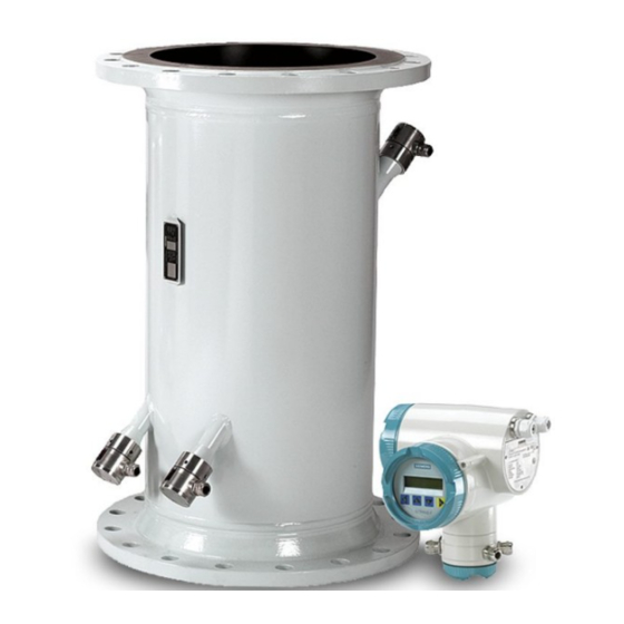
SITRANS F US SONOFLO
Ultrasonic flowmeter
Sensor type SONO 3300 and SONO 3100
Signal converter type SONO 3000
Technical Documentation (handbooks, instructions, manuals etc.) for the complete product
range SITRANS F can be found on the internet/intranet via the following link:
English: http://www4.ad.siemens.de/WW/view/en/10806951/133300
Order no.: FDK:521H0409
SFIDK.PS.029.Q3.02
[
Handbook
Edition 01/2006 - Revision 02
® ® ® ® ®
085R9401
]
Advertisement
Table of Contents

Related Manuals for Siemens SITRANS F US SONOFLO SONO 3300


Summary of Contents for Siemens SITRANS F US SONOFLO SONO 3300
- Page 1 Sensor type SONO 3300 and SONO 3100 Signal converter type SONO 3000 Technical Documentation (handbooks, instructions, manuals etc.) for the complete product range SITRANS F can be found on the internet/intranet via the following link: English: http://www4.ad.siemens.de/WW/view/en/10806951/133300 Order no.: FDK:521H0409 085R9401 SFIDK.PS.029.Q3.02...
- Page 2 ® ® ® ® ® SITRANS F US SONOFLO Siemens Flow Instru- Mild steel Stainless and SONOKIT ments range of ultra- Standard program mild steel sonic flowmeters Extended program Sensor SONO 3300 SONO 3100 Size [ [ [ [ [ mm] ] ] ] ]...
-
Page 3: Table Of Contents
® ® ® ® ® SITRANS F US SONOFLO Contents Introduction Precision measuring system ..........................4 Handling ................................4 System overview ..............................4 Technical data System accuracy ..............................5 Signal converter SONO 3000 ..........................6 Sensor SONO 3300 ............................8 Sensor SONO 3100 ............................ -
Page 4: Introduction
® ® ® ® ® SITRANS F US SONOFLO 1. Introduction 1. Introduction ® Siemens Flow Instruments SITRANS F US SONOFLO ultrasonic flowmeters are designed for measurement of: • Volume flow rate • Total volume • Sound velocity in the media ®... -
Page 5: Technical Data
® ® ® ® ® SITRANS F US SONOFLO 2. Technical data Technical data 2.1 System accuracy Reference conditions: • Fluid: Water • Fluid temperature: 22 ±5 °C • Ambient temperature: 22 ±5 °C • Supply voltage: 115-230 V a.c. +10% to −15% 24 V d.c. -
Page 6: Signal Converter Sono 3000
® ® ® ® ® SITRANS F US SONOFLO 2. Technical data 2.2 Signal converter Terminal connection SONO 3000 Analog output Individually galvanically isolated, 31 and 32 isolation voltage 500 V Measurement of: (optional via menu) Volume flow, sound velocity 33 and 34 Current 0-20 mA or 4-20 mA... - Page 7 ® ® ® ® ® SITRANS F US SONOFLO 2. Technical data Enclosure IP 65, Enclosure IP 65 to IEC 529 and DIN 40050 wall mounting Material Standard 19" insert in aluminium/steel (DIN 41494) Mechanical vibration 1G 1-800 Hz sinusoidal in all directions to IEC 68-2-6 Ambient temperature Operation: +0 °C to +55 °C...
-
Page 8: Sensor Sono 3300
DN 50 to DN 1200: PN: EN 1.0025-S235JRG2 Class: ASTM A105 Transducer Stainless steel Material certificate The sensor is supplied as standard with a Siemens Flow Instruments certificate of conformity (standard). Material certificate on wetted parts on request NDT examination report Available on request Max. -
Page 9: Sonokit Mounting Kit
® ® ® ® ® SITRANS F US SONOFLO 2. Technical data 2.5 SONOKIT mounting Introduction 1-track or 2-tracks sensor supplied as a kit for mounting on existing pipelines Description DN 200 to DN 4000 (8" to 160") Line pressure Max. -
Page 10: Sizing Table (Dn 50 To Dn 4000)
® ® ® ® ® SITRANS F US SONOFLO 2. Technical data 2.7 Sizing table (DN 50 to DN 4000) SFIDK.PS.029.Q3.02... -
Page 11: Dimensions And Weight
® ® ® ® ® SITRANS F US SONOFLO 3. Dimensions and weight Signal converter wall mounted Dimensions and weight 3.1 Signal converter SONO 3000 IP 67 Weight: SONO 3000 approx. 2.0 kg Signal converter shown with wall bracket Weight: Wall bracket with pipe clamp approx. 1.6 kg 3.2 Sensor SONO 3100 A. -
Page 12: Sono 3100 Approximate System Weights [Kg]
® ® ® ® ® SITRANS F US SONOFLO 3. Dimensions and weight PN 6 PN 10 PN 16 PN 25 PN 40 θ *) D *) D *) D *) D Flange Flange Flange Flange Flange dia. dia. dia. dia. -
Page 13: Sensor Installation
® ® ® ® ® SITRANS F US SONOFLO 4. Sensor installation Sensor installation To ensure optimum performance it is essential that the following instructions are followed. 4.1 Location The SONO 3300/3100 sensor can be installed both inside or outside, even in exposed conditions. The sensor is suitable for media and ambient temperatures from −50 to +160°C. -
Page 14: Installation In Vertical Pipes
® ® ® ® ® 4. Sensor installation SITRANS F US SONOFLO 4.5 Installation in vertical Recommended direction of flow: upwards. This pipes will minimize the effect of gas/air bubbles on the measurement. U-shaped sensor type SONO 3100 must only be mounted in a vertical position when the medium can be guaranteed free of air bubbles and particles, otherwise loss of signal can occur. -
Page 15: Measuring Liquids Containing Abrasive Or Other Particles
Recommended outlet: 3 x pipe diameter. If more bends than one, please contact Siemens Flow Instruments for advice. Permissible pressure Maximum permissible pressure and temperature for Siemens Flow Instruments ultrasonic flowmeters and temperature can be seen on the sensor label. Flanges according to PN Flanges and joints as well as related pressure/temperature (p/t) classification have been described in EN 1092. -
Page 16: Installation Of Transducer Type Sono 3200
® ® ® ® ® 4. Sensor installation SITRANS F US SONOFLO 4.11 Installation of The transducer type SONO 3200 for use with sensor type SONO 3100 and retrofitting kit type transducer type SONOKIT. SONO 3200 Transducer type SONO 3200 are available in two variants: Flange type: The transducer has a DIN flange with grove for fitting to a corresponding flange welded onto the pipe. -
Page 17: Accessories
® ® ® ® ® SITRANS F US SONOFLO 4. Sensor installation 4.12 Accessories Extraction tool Transducer SONO 3200 O-ring type can be removed from the pipe section without draining the pipe using the extraction tool. Extraction tool specification Connection: BSP 1 1/2 internal Max. -
Page 18: Signal Converter Installation
® ® ® ® ® SITRANS F US SONOFLO 5. Signal converter installation Signal converter Removal of display window (24 V version) installation All signal converter readings are accessed by pressing the rubber button on the display win- dow. When setting the converter or turning the 5.1 Signal converter keypad the display window must be removed. -
Page 19: Installation Of The Signal Converter In Compact Mode
® ® ® ® ® SITRANS F US SONOFLO 5. Signal converter installation With compact installation the temperature of 5.2 Installation of the the liquid must not exceed +120°C and the signal converter in . = 120 °C compact mode ambient temperature must not exceed +50°C. -
Page 20: Remote Installation Of The Signal Converter
® ® ® ® ® SITRANS F US SONOFLO 5. Signal converter installation 5.3 Remote installation of With remote installation, the distance between the signal converter sensor and signal converter must not exceed 20 m when using multi-coaxial cable. Is a longer distance required use of coaxial cable is recommended. -
Page 21: Wall Bracket For Use With 4 Single-Core Coaxial Cables
® ® ® ® ® SITRANS F US SONOFLO 5. Signal converter installation 5.5 Wall bracket for use 3. Connect track 1 to transducers C and D and with 4 single-core track 2 to transducers A and B. See "Electrical coaxial cables connections"... -
Page 22: 19" Insert
® ® ® ® ® SITRANS F US SONOFLO 5. Signal converter installation 19" insert The 19" insert is designed for installation in a 19" rack. The insert has a width of 28 TE (142 mm), a height of 3 U (128 mm) and a module depth of 160 mm. The insert can be installed directly in a 19"... -
Page 23: Front Of Panel Mounting
® ® ® ® ® SITRANS F US SONOFLO 5. Signal converter installation 5.6.3 Front of panel mounting 1. Mount the connection plate in the panel set using 4 screws. 2. Mount the panel set as shown in the figure. ®... -
Page 24: Signal Converter Sono 3000 19" Rack
® ® ® ® ® SITRANS F US SONOFLO 5. Signal converter installation 5.7 Signal converter Signal converter as insert for 19" rack module SONO 3000 19" rack Weight: SONO 3000 approx. 2.8 kg SONO 3000 19" rack module shown with IP 65 wall mounting enclosure Weight: 19"... -
Page 25: Connection Board 19" Insert
® ® ® ® ® SITRANS F US SONOFLO 5. Signal converter installation 5.8 Connection board 19" insert 5.9 IP 65 wall mounting box connection The number of connection opportunities depends on the version type. SFIDK.PS.029.Q3.02... -
Page 26: Setting The Voltage Selector 19" Insert
® ® ® ® ® SITRANS F US SONOFLO 5. Signal converter installation 5.10 Setting the voltage selector 19" insert The voltage selector is located on the back of the signal converter. Settings of 115 V a.c. or 230 V a.c. can be chosen. 5.11 Location of ®... -
Page 27: Sono 3000 Ex Version
® ® ® ® ® SITRANS F US SONOFLO 5. Signal converter installation 5.12 SONO 3000 Ex An Ex version of the SONO 3000 can be installed in areas of high explosion risk as a compact unit version or mounted remotely where installation conditions demand, i.e. the sensor and signal converter can be installed separately at a distance of up to 15 m. -
Page 28: Electrical Connection For "Flame-Proof Housing" Compact Version
® ® ® ® ® SITRANS F US SONOFLO 5. Signal converter installation 5.12.5 Electrical connec- tion for "flame- proof housing" compact version 5.12.6 Electrical connec- tion diagram compact version Supply voltage 230 V a.c. 115 to 230 V a.c. is connected to terminals 1 and 2. The ground wire must be connected to the ground terminal on the terminal plate. -
Page 29: Remote Installation Of Signal Converter
® ® ® ® ® SITRANS F US SONOFLO 5. Signal converter installation 5.12.7 Remote installation The remote version is installed as shown in the figure. The electronics and the display/keypad unit of signal converter can be positioned in the same way as those for the compact version. 5.12.8 Electrical connec- Electrical connections are made in the terminal housing located on the wall fitting. -
Page 30: Electrical Connection Diagram
® ® ® ® ® SITRANS F US SONOFLO 5. Signal converter installation 5.12.9 Electrical connec- tion diagram Supply voltage 230 V a.c. 115 to 230 V a.c. is connected to terminals 1 and 2. The ground wire must be connected to the ground terminal on the terminal plate. -
Page 31: Operation
® ® ® ® ® SITRANS F US SONOFLO 5. Signal converter installation 5.12.10 Operation Operation is identical for both versions, the same menu structure being used for all SITRANS F US ® SONOFLO variants. To protect the keypad and display the front is protected with a glass cover which can be screwed off by hand, i.e. -
Page 32: Location Of The Sensorprom Flow Memory Unit, Remote Mounting
® ® ® ® ® SITRANS F US SONOFLO 5. Signal converter installation 5.12.13 Location of the ® ® ® ® ® SENSORPROM flow memory unit, remote mounting ® ® ® ® ® Location of the SENSORPROM unit. ® 4. Take the SENSORPROM unit out of the antistatic bag. -
Page 33: Electrical Connections
® ® ® ® ® SITRANS F US SONOFLO 6. Electrical connections Electrical connections 6.1 SONO 3000 IP 67 compact mounted 6.2 SONO 3000 IP 67 remote mounted Connect coax cable to 81, 83, 85 and 87. SFIDK.PS.029.Q3.02... -
Page 34: 19" Insert With: 3 Current Outputs, 2 Frequency/Pulse Outputs
® ® ® ® ® SITRANS F US SONOFLO 6. Electrical connections 6.3 19" insert with: 3 current outputs, 2 frequency/pulse outputs Connect coax cable to 81, 83, 85 and 87. Supply voltage 230 V a.c. 115 to 230 V a.c. is connected to terminals 1 and 2. The ground wire must be connected to the ground terminal on the terminal plate. -
Page 35: Frequency Output With A Load > 10Kω
® ® ® ® ® SITRANS F US SONOFLO 6. Electrical connections 6.4 Frequency output with a load > > > > > 10kΩ Ω Ω Ω Ω If the load exceeds > 10kΩ it is recommended to connect a resistor to the frequency output as shown on the figure above. -
Page 36: Starting Up
® ® ® ® ® 7. Starting up SITRANS F US SONOFLO Starting up 7.1 Keypad and display layout Keypad The keypad is used to set the flowmeter. The function of the keys are as follows: TOP UP This key always returns the display to the OPERATOR MENU showing flow. -
Page 37: Menu Build-Up
® ® ® ® ® SITRANS F US SONOFLO 7. Starting up 7.2 Menu build-up The menu structure of the SONO 3000 signal converter is shown in an overview map and in detail by the build-up of each submenu. The menu is built up in two parts. An OPERATOR MENU and a SETUP MENU. Access to the SETUP MENU is, by pressing the TOP-UP key for 2 seconds. -
Page 38: Menu Overview
® ® ® ® ® 7. Starting up SITRANS F US SONOFLO 7.3 Menu overview SFIDK.PS.029.Q3.02... -
Page 39: Sub Menus
® ® ® ® ® SITRANS F US SONOFLO 7. Starting up User code setup The user code can be changed in this menu. The code is factory-set at 1000. If the user code is lost, the factory setting can be re-established as follows: Switch off supply voltage, press the TOP-UP key and switch on the supply voltage. - Page 40 ® ® ® ® ® 7. Starting up SITRANS F US SONOFLO Mass flow ® For SONO 3000 not fitted with a SENSORPROM unit the display indication must be formatted. It is done as follows: a) Sensor ≤ DN 2000: In the menu "MAX.
- Page 41 ® ® ® ® ® SITRANS F US SONOFLO 7. Starting up Totalizer Internal Select flow, direction and engineering units. By selecting bidirectional flow the net flow, i.e. the difference between the positive and the negative flows, will be displayed. Low flow cut-off can be set over a range from 0 - 9.9% of the measuring range.
- Page 42 ® ® ® ® ® 7. Starting up SITRANS F US SONOFLO Frequency/pulse output FRQ./ PULSE FRQ./PULSE FRQ./PULSE VOLUME FLOW FRQ./PULSE PULSE UNIT MASS FLOW BIDIRECTIONAL PULSE OUTPUT UNIDIRECTIONAL FRQ. OUTPUT VOLUME PULSE WIDTH PULSE XXXXXXXX XXXX UUUU UUUU SOUND VELOCITY FRQ./PULSE FRQ.
- Page 43 ® ® ® ® ® SITRANS F US SONOFLO 7. Starting up Relay The relay can be set to indicate flow direction, sound limit or error. The error output is only available on relay no. 1. The sound limit is defined in the mass flow submenu. Select scaled mass flow and enter SOUND VELOCITY 1 and SOUND VELOCITY 2.
- Page 44 Using the SONO 3000 as a four-tracks system is beyond the scope of this handbook. Please contact Siemens Flow Instruments for further information. There is a connection between the number of tracks and which tracks may be set. If installed as a one-track meter, the meter uses only the values set in track 1.
- Page 45 ® ® ® ® ® SITRANS F US SONOFLO 7. Starting up Length The track length (L) is the distance between the two transducer windows in the same track. Angle of ultrasonic track The angle (θ) is the track angle, i.e. the angle between the track and centerline of the pipe. Retrofitting kit type SONOKIT will as standard have an angle close to 60°.
-
Page 46: Factory Settings
® ® ® ® ® 7. Starting up SITRANS F US SONOFLO ® 7.5 Factory settings On start-up the meter uses the factory default setting in the SENSORPROM unit. The following tables state the factory-set values. The range for each setting is given. If the respective setting range is exceeded, the cursor moves to the first digit in the display and flashes to indicate the setting is invalid. - Page 47 ® ® ® ® ® SITRANS F US SONOFLO 7. Starting up Table 1 Default settings Settings available (continued) Frq. 2/Pulse 2 Volume flow, mass flow, sound velocity, off Frq. 2/Pulse 2 direction Unidirectional Unidirectional, bidirectional Frq. 2/Pulse 2 Pulse Frq., pulse L, L ×...
-
Page 48: Max. Ranges And Factory Settings Where Applicable
® ® ® ® ® 7. Starting up SITRANS F US SONOFLO 7.6 Max. ranges and factory settings where applicable Table 2 Volume flow Massflow Volume/ Pulse Totalizer Mass/ Pulse Totalizer max. max. [mm] [inch] Factory Min. Max. Unit Pulse unit unit Factory... -
Page 49: Starting Up Procedure With Sensorprom Flow Memory Unit
® ® ® ® ® SITRANS F US SONOFLO 7. Starting up 7.7 Starting up procedure 1. Switch on the signal converter SONO 3000. The meter will automatically run through a self-test ® ® ® ® ® with SENSORPROM routine. During the self-test the display will show the text ROM TEST, RAM TEST and INITIA- flow memory unit LIZING. -
Page 50: Trouble Shooting
® ® ® ® ® SITRANS F US SONOFLO 8. Trouble shooting 8. Trouble shooting The signal converter is self-monitoring and registers the following faults: 1. The ultrasonic signals and the application. 2. Cable fault on sensor cable and current output loop. 3. -
Page 51: Fault Location Guide
) Alarm if signal level falls below 500 mV (see "Service"). ) Not permitted with calibrated and sealed flowmeters. Please contact Siemens Flow Instruments or send the signal converter and sensor to Siemens Flow Instruments for repair and renewed calibration. -
Page 52: Service Menu
® ® ® ® ® 9. Service SITRANS F US SONOFLO Service The SERVICE MENU contains three sub menues. INFORMATION, FORCE OUTPUT and SIGNAL INFORMATION. INFORMATION contains all identification data of the signal converter and sensor. 9.1 Service menu Note that the meter continues to measure and up-dates the output(s) being in the service menu. The only exception is when an output is set in the FORCE OUTPUT MENU. -
Page 53: Signal Recognition
100 and the meter still operates, this is satisfactory. If the RESONANCE LEVEL is below 20 and the meter is not measuring, (error code 5, 6 and 26), check cable connections and manually check transducers. Please contact Siemens Flow Instruments to establish. MAX. -
Page 54: Ordering
® ® ® ® ® SITRANS F US SONOFLO 10. Ordering Ordering Please look on our homepage http://www.siemens.com/flow under "Product Selector". Please use online Product selector to get latest updates. Product selector link: http://www.pia-selector.com - this page has been updated 2006.03.15... -
Page 55: Sensorprom Memory Unit For Sono 3110
If you order this device, you have to give information regarding the pipe geometry of FDK:085B5329 SONO 3110 the sensor. Please contact Siemens Flow Instruments to get a filling in formula. 10.2 Signal converter SONO 3000 Description Version... -
Page 56: Accessories
® ® ® ® ® SITRANS F US SONOFLO 10. Ordering Transducers SONO 3200 (complete unit) Transd. Material Gasket Pressure Terminal Approval Temp. Length Code Symbol type rating housing range °C O-ring 316 SS O-ring PN 40 Plastic PA 6.6 -20/+100 FDK:085B5306 O-ring... -
Page 57: Accessories For Sitrans F Us Sonoflo ® Ultrasonic Flowmeter
® ® ® ® ® SITRANS F US SONOFLO 10. Ordering ® 10.6 Accessories for SITRANS F US SONOFLO ultrasonic flowmeter 10.6.1 Submersible kit Type/description Code No. Symbol Submersible kit , IP 68 10 m w.g. rating FDK:085L2403 10.6.2 Accessories for Type/description Code No. -
Page 58: Accessories For Sono 3100 And Sonokit
® ® ® ® ® SITRANS F US SONOFLO 10. Ordering 10.7 Accessories for SONO 3100 and SONOKIT 10.7.1 Tools for SONO Type/description Length Code No. Symbol 3100 and SONOKIT Extration tool for replacement of 50 mm transducers FDK:085B5331 SONO 3200 O-ring transducers under pressure (hot-tap) 160 mm transducers FDK:085B5333... - Page 59 ® ® ® ® ® SITRANS F US SONOFLO SFIDK.PS.029.Q3.02...
- Page 60 Suggestions for improvement registration of a utility model or design, are reserved. are always welcomed. Technical data subject to change without prior notice. Copyright © Siemens AG 05.2002 All Rights Reserved Siemens Flow Instruments A/S Order no.: FDK:521H0409-01 Nordborgvej 81...
Need help?
Do you have a question about the SITRANS F US SONOFLO SONO 3300 and is the answer not in the manual?
Questions and answers