Sign In
Upload
Download
Table of Contents
Contents
Add to my manuals
Delete from my manuals
Share
URL of this page:
HTML Link:
Bookmark this page
Add
Manual will be automatically added to "My Manuals"
Print this page
×
Bookmark added
×
Added to my manuals
Manuals
Brands
Siemens Manuals
Measuring Instruments
S7-1200 PLC
Demo software user notes
Siemens S7-1200 PLC Demo Software User Notes
Flowmeter, simatic tia portal v12 getting started software
Hide thumbs
1
Table Of Contents
2
3
4
5
6
7
8
9
10
11
12
13
14
15
16
17
18
19
20
21
page
of
21
Go
/
21
Contents
Table of Contents
Bookmarks
Table of Contents
Table of Contents
Preface
Further Support
Software and Hardware Requirements
System Overview
SIMATIC TIA PORTAL Blocks
Block Call OB1
Block Call FB95
Read Commands
Write Commands
Reading Totalizer - Example
Factory Communications Parameters
HMI Screens
Screen: 000_Main
Screen: 100_Setup
Screen: 101_Access_Level
Screen: 110_Flow_Setup
Screen: 120_Zero_Point_Adjust
Screen: 131_Aerated_Flow
Screen: 132_Aerated_Flow
Screen: 140_Totalizer
Screen: 200_Identification
Screen: 300_Operating
Screen: 310_Process_Variables
Screen: 311_Mass_Flow_Trend
Screen: 400_Diagnose
Screen: 410_Device_Diagnostic
Screen: 420_Alarms
Advertisement
Quick Links
1
Table of Contents
2
Software and Hardware Requirements
3
Simatic Tia Portal Blocks
4
Block Call Ob1
5
Read Commands
6
Screen: 000_Main
Download this manual
SITRANS FC410 CORIOLIS FLOWMETER
SIMATIC TIA PORTAL V12
getting started software
S7-1200 PLC
© Siemens A/S, Flow Instruments, I IA SC PI 3 PRM
Page 1 of 21
File: SITRANS FC410 Demo software user notes for SIMATIC TIA PORTAL V1.1.doc
Table of
Contents
Previous
Page
Next
Page
1
2
3
4
5
Advertisement
Table of Contents
Need help?
Do you have a question about the S7-1200 PLC and is the answer not in the manual?
Ask a question
Questions and answers
Related Manuals for Siemens S7-1200 PLC
Measuring Instruments Siemens simatic s7-400 FM 450-1 User Manual
Counter module (130 pages)
Measuring Instruments Siemens SIRIUS Configuration Manual
Load feeders (98 pages)
Measuring Instruments Siemens SITRANS F Compact Operating Instructions
Coriolis flowmeters; with hart (7me4613, 7me4603, 7me4623, 7me4713) (97 pages)
Measuring Instruments Siemens SITRANS F Operating Instructions Manual
Electromagnetic flowmeters (72 pages)
Measuring Instruments Siemens SITRANS F Hardware Installation Instructions
Ultrasonic flowmeter clamp-on communications module (26 pages)
Measuring Instruments Siemens SITRANS F Instruction Manual
Ultrasonic flowmeters (306 pages)
Measuring Instruments Siemens SITRANS F Programming Manual
Ultrasonic flowmeters si-ware (218 pages)
Measuring Instruments Siemens SITRANS F Operating Instruction
Coriolis flowmeters (46 pages)
Measuring Instruments Siemens SITRANS F Operating Instructions Manual
Ultrasonic flowmeters portable flowmeter (278 pages)
Measuring Instruments Siemens SITRANS F Operating Instructions Manual
Coriolis flowmeters with hart (225 pages)
Measuring Instruments Siemens SITRANS F Operating Instructions Manual
Ultrasonic flowmeters (190 pages)
Measuring Instruments Siemens SIMATIC S7-1200 Manual
Energy meter 480vac (17 pages)
Measuring Instruments Siemens SITRANS F US Operating Instructions Manual
Ultrasonic flowmeter for use with sensor type sono 3100, sono 3300 and sonokit 1- and 2-tracks (52 pages)
Measuring Instruments Siemens SITRANS F US Hardware Installation Instructions
Ultrasonic flowmeters clamp-on communications module (26 pages)
Measuring Instruments Siemens SICAM Manual
Fault passage indicator (52 pages)
Measuring Instruments Siemens SITRANS F Series Operating Instructions Manual
(40 pages)
Summarization of Contents
Preface
Further Support
Software and Hardware Requirements
System Overview - Hardware
SIMATIC TIA PORTAL Software
Block Call OB1
Explains OB1 calling FC94 for Modbus initialization and FC95 for command execution.
Block Call FB95
Details FB95 executing read/write commands using MB_master and storing data in DB_FLOW_PARA (DB17).
Read Commands
Lists commands programmed in FB95 for reading process values, identification, totalizer, diagnostics, setup, and alarm status.
Write Commands
Lists commands programmed in FB95 for writing to totalizer, zero point, setup, and aerated flow parameters.
Reading Totalizer - Example
Demonstrates reading the totalizer value using DB17.DBX128.2 and command 220 for FB95.
Factory Communications Parameters
HMI Screens
Main Screen (000_main)
Displays the main screen with navigation buttons like Main, Setup, Identification, Operating, and Diagnose.
Setup Screen (100_Setup)
Shows the setup screen with quick select options for Flow setup, Zero point adjustment, Aerated flow, and Totalizer.
Access Level Screen (101_Access_level)
Displays the access level screen, showing 'Logged Out' and options to Read, Log In, and Log Out.
Flow Setup Screen (110_Flow_setup)
Presents the flow setup screen with parameters like low mass/volume flow cutoff, process noise damping, and flow direction.
Zero Point Adjustment Screen (120_Zero_Point_Adjust)
Shows the zero point adjustment screen with fields for adjust time, offset value, and standard deviation.
Aerated Flow Screen 1 (131_Aerated_FLOW)
Displays aerated flow parameters, including alarm/warning limits and sample time, with an aerated flow filter option.
Aerated Flow Screen 2 (132_Aerated_FLOW)
Details aerated flow settings, specifically filter time constant, start hysteresis, and minimum filtering time.
Totalizer Screen (140_Totalizer)
Presents the totalizer screen showing the totalizer value and options to read or reset it.
Identification Screen (200_Identification)
Displays the identification screen, showing the sensor serial number.
Operating Screen (300_Operating)
Shows the operating screen with a quick select option for Process Variables.
Process Variables Screen (310_Process_Variables)
Displays process variables like Mass Flow, Volume Flow, Density, and Temperature with units.
Mass Flow Trend Screen (311_Mass_Flow_trend)
Shows a trend graph for Mass Flow, displaying current value and time stamps for the trend.
Diagnose Screen (400_Diagnose)
Presents the diagnose screen with quick select options for Device diagnostic and Alarms.
Device Diagnostic Screen (410_Device_Diagnostic)
Displays device diagnostic information, including driver current, pick-up amplitudes, and sensor frequency.
Alarms Screen (420_Alarms)
Shows alarm information, including alarm groups, quality codes, and process values for quality codes.
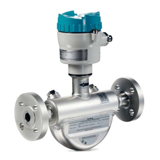
Table of Contents
Print
Rename the bookmark
Delete bookmark?
Delete from my manuals?
Login
Sign In
OR
Sign in with Facebook
Sign in with Google
Upload manual
Upload from disk
Upload from URL
Need help?
Do you have a question about the S7-1200 PLC and is the answer not in the manual?
Questions and answers