Texas Instruments CC1110 User Manual
Mini development kit
Hide thumbs
Also See for CC1110:
- Design manual (9 pages) ,
- Quick start manual (7 pages) ,
- Quick start instructions (3 pages)
Table of Contents
Advertisement
Quick Links
Advertisement
Table of Contents

Subscribe to Our Youtube Channel
Related Manuals for Texas Instruments CC1110


Summary of Contents for Texas Instruments CC1110
- Page 1 CC1110 & CC2510 Mini Development Kit User’s Guide SWRU236a...
-
Page 2: Table Of Contents
DEBUG C (DEBUG) ....................11 ONNECTOR I/O P (INTIO)....................12 ONNECTORS .........................12 NTENNA PTIONS ....................13 ARDWARE EVELOPMENT USING SMARTRF STUDIO WITH SMARTRF CC1110/CC2510 TARGET BOARDS ..14 TX P ......................17 ESTING ARAMETERS RX P ......................17 ESTING ARAMETERS ......................17 INK AND ANGE TESTING USING SMARTRF PACKET SNIFFER WITH SMARTRF CC1110/CC2510 TARGET BOARDS ...............................19... -
Page 3: Introduction
CC1110 operates in the sub-1 GHz unlicensed ISM bands while the CC2510 operates in the 2.4 GHz unlicensed ISM bands. The CC1110 and CC2510 combine the excellent performance of the state-of-the-art CC1101 and CC2500... -
Page 4: About This Manual
TI web site, see [4] and [5]. The CC1110 Mini Development Kit 868-915 MHz Quick Start Guide [1] and the CC2510 Mini Development Kit Quick Start Guide [2] are short tutorials on how to quickly and easy get started with the two mini development kits and how to use the preprogrammed link test on the kits. -
Page 5: Acronyms
Light Emitting Diode LPRF Low Power RF Micro Controller Printed Circuit Board Random Access Memory Radio Frequency Receive System on Chip Serial Peripheral Interface Short Range Device Texas Instruments Transmit UART Universal Asynchronous Receive Transmit Universal Serial Bus Printed Circuit Board 5/26... -
Page 6: Mini Development Kit Content
CC1110 or CC2510 performance. They further offer a complete platform to develop prototype RF systems. • Evaluate the CC1110/CC2510 right out of the box. The kits can be used for range testing using the pre-programmed link test. •... - Page 7 RF IC, necessary external components, battery holders, LEDs, and a PCB antenna. The module is pre-programmed with a link test for easy use. The board further includes user I/Os and access to CC1110 peripherals. • CC1110 DEBUG interface •...
-
Page 8: Getting Started
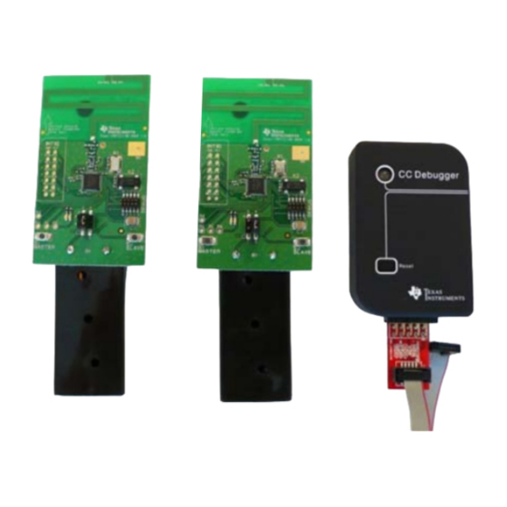
CC Debugger. The SmartRF CC1110/CC2510 target board includes interfaces for programming and debugging the CC1110/CC2510 via the small connector marked “Debug”. The boards further provide access to all the I/O signals from the CC1110/CC2510, two LEDs and two push buttons. 8/26... - Page 9 After assembling the hardware, there are several options for working with the CC1110 and CC2510 devices: • Run the link test application that is preprogrammed on the CC1110’s/CC2510’s. The CC1110 Mini Development Kit 868-915 MHz Quick Start Guide [1] or the CC2510 Mini Development Kit Quick Start Guide [2] included in the kits describes the necessary steps to run this application.
-
Page 10: Using The Hardware
CC Debugger. The desired power source is selected with a jumper on the power selection connector P1. Figure 6-2 – The power selection connector on the SmartRF CC1110 and the SmartRF CC2510 target boards All power sources are disconnected when no jumper short either pin 1-2 or 3-4 on the power selection connector. -
Page 11: External Power Supply
The pre-programmed link test is optimized for making a robust link and is thus not power optimized; see more in the CC1110 & CC2510 Mini DK Software Example User’s Guide [3]. For this reason, due to limitations of coin cell batteries, it is not recommended to run the preprogrammed link test SW on a coin cell battery. -
Page 12: I/O Pin Connectors (Intio)
The PCB antenna can optionally be disconnected by turning the R1 resistor on SmartRF CC1110 target board or the R2 resistor on the SmartRF CC2510 target board 90 degrees from the PCB antenna position to a test point. By turning the R1/R2 resistor to the test point... -
Page 13: Hardware Development
GHz band. The optimal antenna length for 915 MHz operation (still with the two AAA batteries in the battery holder) is shown in the silk print on the SmartRF CC1110 target boards. Removing the two AAA batteries from the battery holder on the board, encapsulating the board etc. -
Page 14: Using Smartrf Studio With Smartrf Cc1110/Cc2510 Target Boards
“CC2510 – new device” respectively. Double click on the new device item, and the window shown in Figure 7-4 and Figure 7-5 will appear. This is the main control panel for the CC1110/ CC2510. In this window, settings can be changed, tests performed and registers adjusted. - Page 15 Figure 7-2 - Start window for the SmartRF CC1110 target board when starting SmartRF Studio Figure 7-3 - Start window for the SmartRF CC2510 target board when starting SmartRF Studio 15/26...
- Page 16 Figure 7-4 - Control window for the SmartRF CC1110 target board from SmartRF Studio Figure 7-5 - Control window for the SmartRF CC2510 target board from SmartRF Studio 16/26...
-
Page 17: Testing Tx Parameters
Studio and set the desired parameters. • Solder a semi rigid cable to test point T2 on the SmartRF CC1110 target board or T3 on the SmartRF CC2510 target board and turn the R1/R2 resistor from the PCB antenna position to the test point position, see more in section 6.6. Connect a 50 Ohm coaxial cable from the spectrum analyzer to the semi rigid cable and use the “Simple TX”... - Page 18 To perform practical range testing with the preprogrammed link test application on the SmartRF CC1110/CC2510 target boards, follow the directions given in the CC1110 Mini Development Kit 868-915 MHz Quick Start Guide [1] or the CC2510 Mini Development Kit Quick Start Guide [2].
-
Page 19: Using Smartrf Packet Sniffer With Smartrf Cc1110/Cc2510 Target Boards
Using SmartRF Packet Sniffer with SmartRF CC1110/CC2510 Target Boards You can use the SmartRF CC1110/CC2510 target boards to capture radio packets with the SmartRF Packet Sniffer [8]. When the board is connected to the CC Debugger, as depicted in Figure 5-2, you can start the Packet Sniffer. - Page 20 Before starting, it is necessary to select the radio settings to use for correct packet capturing. These are the RF register settings which will be written to the CC1110 before it starts to receive packets. The register settings can be exported from SmartRF Studio in a format that the SmartRF Packet Sniffer is capable of understanding.
-
Page 21: Software Application Examples
Development Kit 868-915 MHz Quick Start Guide [1], the CC2510 Mini Development Kit Quick Start Guide [2] and the CC1110 & CC2510 Mini DK Software Example User’s Guide [3]. Refer to the CC Debugger [6] and SmartRF Flash Programmer [12] User’s Guides for more information regarding these tools. -
Page 22: Frequently Asked Questions
CC1110/CC2510 target boards. Nothing happens when I power up the board. Make sure that the jumper on the P1 header on the SmartRF CC1110/CC2510 board is set in the correct position. Please refer to section 6.1 for correct jumper setting. -
Page 23: References
11 References CC1110 Mini Development Kit 868-915 MHz Quick Start Guide http://www.ti.com/lit/swru234 CC2510 Mini Development Kit Quick Start Guide http://www.ti.com/lit/swru235 CC1110 & CC2510 Mini DK Software Example User’s Guide http://www.ti.com/lit/swru237 CC1110 Mini Development Kit 868-915 MHz website http://focus.ti.com/docs/toolsw/folders/print/cc1110dk-mini-868.html CC2510 Mini Development Kit website http://focus.ti.com/docs/toolsw/folders/print/cc2510dk-mini.html... -
Page 24: Document History
swru236a 12 Document history Revision Date Description/Changes Updated links, added information regarding how to extend the code size limited IAR swru236a 2009-11-17 Embedded Workbench for 8051 version 7.51A and above so that it can be used with SimpliciTI. swru236 2009-07-17 First revision. -
Page 25: Asmartrf Cc1110 Target Board
SmartRF CC1110 Target Board 25/26... -
Page 26: Bsmartrf Cc2510 Target Board
swru236a SmartRF CC2510 Target Board 26/26... - Page 27 IMPORTANT NOTICE Texas Instruments Incorporated and its subsidiaries (TI) reserve the right to make corrections, modifications, enhancements, improvements, and other changes to its products and services at any time and to discontinue any product or service without notice. Customers should obtain the latest relevant information before placing orders and should verify that such information is current and complete.
- Page 28 Mouser Electronics Authorized Distributor Click to View Pricing, Inventory, Delivery & Lifecycle Information: Texas Instruments CC2510DK-MINI...
Need help?
Do you have a question about the CC1110 and is the answer not in the manual?
Questions and answers