Table of Contents
Advertisement
Advertisement
Table of Contents

Related Manuals for Texas Instruments CC2530 ZigBee Development Kit


Summary of Contents for Texas Instruments CC2530 ZigBee Development Kit
-
Page 1: Cc2530 Zigbee Development Kit User's Guide
CC2530 ZigBee Development Kit User’s Guide swru209b... -
Page 2: Table Of Contents
Table of contents CC2530 ZIGBEE DEVELOPMENT KIT USER’S GUIDE ................1 INTRODUCTION............................. 3 ABOUT THIS MANUAL ......................... 3 ACRONYMS ............................. 4 ZIGBEE DEVELOPMENT KIT CONTENTS ..................5 GETTING STARTED ..........................7 ........................7 ETTING UP THE HARDWARE ................8... -
Page 3: Introduction
[2] [3]. Please visit the CC2530 ZigBee Development Kit [11] web page and CC2530 product page [1] for additional information. Further information can be found on the TI LPRF Online Community [16]. -
Page 4: Acronyms
Low Power RF Micro Controller Not connected Packet Error Rate Radio Frequency Receive System on Chip Serial Peripheral Interface Short Range Device Texas Instruments Transmit UART Universal Asynchronous Receive Transmit Universal Serial Bus ZigBee Development Kit Z-Stack TI’s ZigBee software implementation 4/28... -
Page 5: Zigbee Development Kit Contents
ZigBee Development Kit contents The CC2530 ZigBee Development Kit (CC2530ZDK) includes hardware and software that allows quick testing of the CC2530 RF performance and offers a complete platform for development of advanced prototype RF systems and ZigBee applications. ... - Page 6 swru209b SmartRF05EB The SmartRF05EB (evaluation board) is the main board in the kit with a wide range of user interfaces: 3x16 character serial LCD Full speed USB 2.0 interface UART LEDs Serial Flash Potentiometer ...
-
Page 7: Getting Started
swru209b Getting started Setting up the hardware After opening the kit, make sure you have all components. Please contact your TI Sales Representative or TI Support [17] if anything is missing. Start by connecting the antennas to the SMA connector on the RF evaluation boards. Tighten the antenna’s screw firmly on to the SMA connector. -
Page 8: Running The Preprogrammed Zigbee Sensor Demo
SmartRF Studio is a PC application developed for configuration and evaluation of many of the RF-IC products from Texas Instruments, including the CC2530. The application communicates with the CC2530 via the USB controller on the SmartRF05EB board. The USB controller uses the debug interface of the CC2530 to execute commands and to read and write registers. - Page 9 swru209b PC. SmartRF Studio also offers a flexible code export function of radio register settings for software developers. Before proceeding, please download and install the latest version of SmartRF Studio from the web [2]. By installing Studio, the USB drivers needed for proper interaction between the PC and the hardware of the CC2530DK will also be installed.
- Page 10 swru209b Figure 4 - CC2530 control panel in SmartRF Studio Figure 4 shows the main control panel for the CC2530. It lets you perform a number of operations: Run TX Test modes for testing of RF output power and spectrum; e.g. by connecting a spectrum analyser or a power meter to the CC2530EM SMA connector to perform RF measurements.
-
Page 11: Developing Your Own Software With The Cc2530
After installation refer to the Z-stack User’s Guide document found in the installation folders of Z- Stack™. The default root installation path for Z-Stack is C:\Texas Instruments\. A software package with the source code for the Sensor Demo, and Intel HEX files ready to be programmed on the devices, is available on the CC2530ZDK web site [11]. -
Page 12: Rf Testing
swru209b RF Testing NB! When running RF performance tests, it is recommended to disable all other peripherals on the SmartRF05EB in order to avoid unwanted noise on the on-board voltage. In particular, make sure the RS232 level converter/line driver is disabled. RF testing can be performed by using SmartRF Studio together with the Development Kit. -
Page 13: Rx Parameter Testing Basics
swru209b RX Parameter Testing Basics To investigate the RX performance of the CC2530, you can use a signal generator or “Packet TX” in SmartRF Studio (with another EB+EM) to generate the packets to receive. The receiver can be configured by using the “Packet RX” test feature in SmartRF Studio. By adding a jammer (a third node that generates either noise on the same channel or a strong signal on an adjacent channel) it is also possible to measure co-channel rejection and selectivity/blocking performance. -
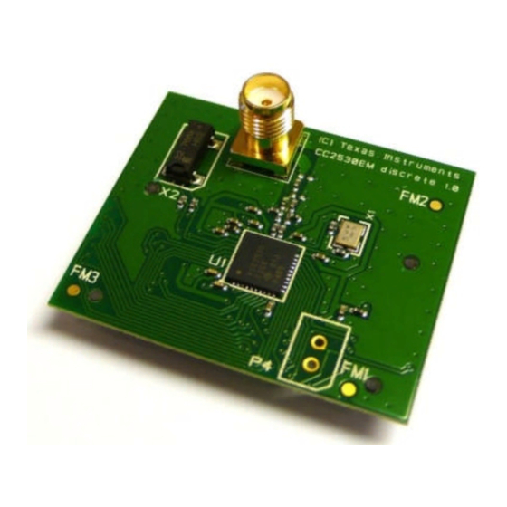
Page 14: Cc2530Em
swru209b CC2530EM SMA antenna connector 32 kHz Crystal 32MHz Crystal CC2530F256 EM Connector (Bottom side) EM Connector (Bottom side) Figure 6 - CC2530 Evaluation Module The CC2530EM is a complete RF module based on one of the recommended reference designs for the CC2530 radio. -
Page 15: Cc2531 Usb Dongle
swru209b CC2531 USB Dongle Meandred F-antenna IO Connector CC2531F256 LEDs Button S2 Button S1 Debug connector Voltage regulator Figure 7 - CC2531 USB Dongle The USB dongle that is included in the kit comes preprogrammed such that it can be used together with the SmartRF Packet Sniffer [4] to capture packets going over the air. - Page 16 swru209b Figure 8 - CC2531 USB Dongle connected to SmartRF05EB The debug connector on the CC2531 USB Dongle matches the debug connector on the SmartRF05EB (and the CC Debugger). Note that, by default, the CC2531 dongle is not powered through the debug connector, so an external power source must be used while programming. The easiest solution is to connect it to a USB port on the PC.
-
Page 17: Smartrf05 Evaluation Board
swru209b SmartRF05 Evaluation Board The SmartRF05 Evaluation Board is thoroughly described in the SmartRF05EB User’s Guide [6]. That document will describe the hardware features in detail and provide the schematics for the board. 17/28... -
Page 18: Smartrf05 Battery Board
swru209b 10 SmartRF05 Battery Board 256kB SPI Flash Module Connectors LEDs Joystick Probe Connectors EM Selection Power Switch Switch Push Buttons Figure 9 SmartRF05 Battery Board The SmartRF05 Battery Board is a smaller and simpler board than the SmartRF05EB. The Battery Board can together with an EM be used as a standalone node. -
Page 19: Joystick
swru209b 10.1 Joystick The joystick detects five positions (centre, up, down, left, right) and one event (pushed). The two aggregated signals, JOY_MOVE and JOY_LEVEL, are used to detect a joystick event when using a SoC (e.g. the CC2530). JOY_MOVE is high whenever the joystick is moved away from the centre position, including pushing. -
Page 20: Em Selection Switch
swru209b Function on BB Pin Pin Function on BB JOYSTICK_PUSH IO_LED2_MSP Not in use on BB IO_LED3_MSP VCC_EM IO_LED4_MSP VCC_EM JOYSTICK_UP Not in use on BB JOYSTICK_LEFT Not in use on BB SoC Debug P3.7 & IO_BUTTON2 Flash Reset Not in use on BB Not in use on BB JOY_MOVE Not in use on BB... - Page 21 swru209b Figure 11 - Switch P8 effect on LED 1-4 Due to lack of pins, some of the signals are shared. The chip select signal to the EM will also be affected when LED3 is used by the SoC (e.g. CC2530). In most cases, this will not be a problem, since the SoC does not, by default, implement a SPI slave.
-
Page 22: Probe Connectors
swru209b 10.4 Probe connectors The probe connectors P4 and P5 bring out all the signals from the EM connectors for probing purposes. The connectors allow easy access to I/O signals and to connect prototyping boards. The pin-out of these connectors are shown below. Function on BB Signal name Signal name... -
Page 23: Current Measurement Jumper
swru209b Figure 13 Program/debug with SmartRF05EB The pin out of this connector is depicted below. For debugging and programming of the SoC the following signals are used; SoC RESET_N, DD and DC. In addition GND and +3.3V shall be connected. Figure 14 SmartRF05BB SoC Debug Connector As seen on Figure 14 also the SPI signals CS, MISO, MOSI and SCLK can be found on this connector. -
Page 24: Frequently Asked Questions
swru209b 11 Frequently Asked Questions When connecting the SmartRF05EB to my PC via USB, the dialog window below appears. Why? What should I do? The SmartRF05EB will be recognized as a USB device by the operating system, and it will ask the user to provide information about which USB driver that should be associated with the device. - Page 25 swru209b How can I measure the current consumption of the CC2530? The easiest way to measure current consumption of the chip in various modes is to connect the EM directly to the SmartRF05EB and disconnect everything on the board that consumes power by removing all jumpers.
-
Page 26: References
[11] CC2530ZDK web site http://focus.ti.com/docs/toolsw/folders/print/cc2530zdk.html [12] CC2530DK Quick Start Guide http://www.ti.com/lit/swra273 [13] CC2530DK User’s Guide http://www.ti.com/lit/swru208 [14] CC2530DK web site http://focus.ti.com/docs/toolsw/folders/print/cc2530dk.html [15] DN002 -- Practical Sensitivity Testing http://www.ti.com/lit/swra097 [16] Texas Instruments Low Power RF Online Community http://www.ti.com/lprf-forum [17] Texas Instruments Support http://support.ti.com 26/28... -
Page 27: Document History
swru209b 13 Document history Revision Date Description/Changes Clarified that IAR EW8051 is required when working with the Z-Stack. Updated screenshots of SmartRF Studio. 2011-04-05 Include updated schematics. Fixed a few typos. 2009-08-04 Added SmartRF05 Battery Board schematics 2009-06-08 First revision. 27/28... -
Page 28: Appendix Aschematics
swru209b Appendix A Schematics Please refer to the following pages for the schematics for CC2530 Evaluation Module CC2531 USB Dongle SmartRF05 Evaluation Board SmartRF05 Battery Board The reference design for the CC2530 evaluation module can be found on the CC2530 web page [1]. 28/28... - Page 29 P0_4 P0_5 DCOUPL P0.6 P0_6 P0.7 RBIAS P0_7 RESET_N PINROW_1x2 SMD_SOCKET_2X10 Reset P1.2 P0.5 P2.0 CONTRACT NO. COMPANY NAME 025104 Texas Instruments APPROVALS DATE CC2530EM Discrete DRAWN SIZE FSCM NO. DWG NO. REV. CHECKED 1.3.1 ISSUED 1 (1) SCALE SHEET...
- Page 30 P1_4 P1_4 P1_5 P1_5 P1_6 P1_6 P1_7 P1_7 P2_1 P2_1 P2_2 P2_2 PA_DM PA_DM PA_DP PA_DP CONTRACT NO. COMPANY NAME 025104 Texas Instruments APPROVALS DATE CC2531 USB dongle DRAWN SIZE FSCM NO. DWG NO. REV. CHECKED ISSUED 1(4) SCALE SHEET...
- Page 31 VBUS From PC TPS76933 R_0_0402 VREG C_1U_0603_X5R_L_6P3 C_0402 C_4U7_0603_X5R_K_6 R_2_0402_F Not mount: C3, R2 CONTRACT NO. COMPANY NAME 025104 Texas Instruments APPROVALS DATE CC2531 USB DONGLE VOLTAGE REGULATOR DRAWN SIZE FSCM NO. DWG NO. REV. CHECKED ISSUED SCALE SHEET 2(4)
- Page 32 P0_3 P0_3 XOSC_Q2 P0_4 P0_4 P0_5 P0_5 DCOUPL P0_6 R201 RBIAS R_2K2_0402_G P0_7 RESET_N RESET_N CONTRACT NO. COMPANY NAME 025104 Texas Instruments APPROVALS DATE CC2531 USB DONGLE RF-PART DRAWN SIZE FSCM NO. DWG NO. REV. CHECKED ISSUED SCALE SHEET 3(4)
- Page 33 P2_1 P1_4 RESET_N P1_5 VCC_EXT P1_6 P1_7 P0_5 P0_4 P0_3 P0_2 CONTRACT NO. COMPANY NAME 025104 Texas Instruments APPROVALS DATE CC2531 USB dongle USB circuitry DRAWN SIZE FSCM NO. DWG NO. REV. Not mount: R92, IO CHECKED ISSUED SCALE SHEET...
- Page 34 PCB_FEET_19 USB Interface Power Supply - CC2511 - Regulators - Power jumpers - CC2511 debug PCB_FEET_19 - Battery - USB port USB_UART_RTS VCC_EM USB_UART_CTS VBUS VBUS PCB_FEET_19 USB_UART_RX USB_UART_TX +3.3V USB +3.3V USB POWER_PS VCC_IO USB_DBG_DD_DIR PCB_FEET_19 USB_DBG_DC USB_DBG_DD USB_CS Sheet 4 USB_MISO USB_IO_RESET...
- Page 35 +3.3V USB USB BUTTON USB SoC Debug +3.3V USB PUSH_BUTTON_SKRK +3.3V USB VCC_IO VCC_IO L_BEAD_102_0603 PINROW_2X5 VCC_IO USB_RESET USB LED LED_CL150YCD CC2511 DVDD 2 C16 DVDD AVDD DGUARD AVDD AVDD_DREG AVDD DCOUPL AVDD P2_0 USB_IO_RESET P2_1 P2_2 P1_0/LED RF_P P1_1/LED USB_DBG_DC P1_2 RF_N...
- Page 36 VCC_IO External SOC Debug SN74AVC4T245 DUT_VCC VCCA EM_DBG_DD_DIR VCCB PINROW_2X5 PINROW_SMD_2X5_1.27MM 1DIR 2DIR DUT_VCC DUT_VCC EM_DBG_DD DUT_DD DUT_DD DUT_DD EM_RESET EM_DBG_DC VCC_EM R_0603 Mount 0 ohm resistor in position R30 to power DUT from +3.3V USB through connector P3 VCC_EM SMD_HEADER_2x10 SMD_HEADER_2x10 SMD_HEADER_2x10...
- Page 37 R_0603 LPS3015-222ML 2.2uH Do Not Mount TPS63030 VCC_EM jumper STRAP_1 VCC_EM VOUT R_0_0603 VINA R_1M0_0603_J PS/SYNC PGND PPAD POWER_PS VCC_IO jumper STRAP_1 VCC_IO 1xAA_1_5V Battery 1xAA_1_5V Switch_6pin Power On/Off 1 2 3 Power source jumper: R_0_0603 1-2: Battery +3.3V USB 2-3: USB/DC (default) R_0603 Do Not Mount...
- Page 38 BUTTON1_POWER_MSP VCC_IO VCC_IO VCC_IO VCC_IO VCC_IO SN74CBTLV3257PW HMC16311SF-PY Switch_6pin HMC_CON IO_LED1 VCC_IO 1 2 3 7 - not use 1 - backlight supply - IO_LED2_MSP 8 - not use 2 - backlight supply + USB_IO_RESET IO_LED2_SOC 12- not use 3 - logic power supply - 13- not use 4 - logic power supply + 14- not use...
- Page 39 VCC_IO C_100N_0603_X7R_K_50 C_100N_0603_X7R_K_50 SN65C3243DBR VCC_IO C_100N_0603_X7R_K_50 C_100N_0603_X7R_K_50 R1IN R2IN R3IN FORCEON R4IN R5IN R_0_0603 T1OUT R2OUTB T2OUT R1OUT EM_UART_RX T3OUT R2OUT T3IN R3OUT T2IN R4OUT T1IN R5OUT DSUB_9F R_0_0603 EM_UART_CTS R_0_0603 EM_UART_TX R_0_0603 EM_UART_RTS PC RS232-port 2-RXD 3-TXD 5-GND 7-RTS 8-CTS CONTRACT NO.
- Page 40 JOYSTICK R_0_0603 R_0_0603 JOYSTICK_UP JOYSTICK_RT VCC_IO right PUSH R_0_0603 CENTRE COMMON JOYSTICK_PUSH push left down C_100N_0603_X7R_K_50 skrhab_e010 R_0_0603 R_0_0603 JOYSTICK_LT JOYSTICK_DN U7-A SN74HC32 U7-B SN74HC32 U7-C SN74HC32 U7-D SN74HC32 JOY_MOVE PUSH VCC_IO VCC_IO R_100K_0603_F R_220K_0603_F U8-A U8-B TLV272 TLV272 R_200K_0603_F R_100K_0603_F JOY_LEVEL R_200K_0603_F...
- Page 44 IMPORTANT NOTICE Texas Instruments Incorporated and its subsidiaries (TI) reserve the right to make corrections, modifications, enhancements, improvements, and other changes to its products and services at any time and to discontinue any product or service without notice. Customers should obtain the latest relevant information before placing orders and should verify that such information is current and complete.
- Page 45 Mouser Electronics Authorized Distributor Click to View Pricing, Inventory, Delivery & Lifecycle Information: Texas Instruments CC2530ZDK...
Need help?
Do you have a question about the CC2530 ZigBee Development Kit and is the answer not in the manual?
Questions and answers