
Subscribe to Our Youtube Channel
Related Manuals for Texas Instruments CC2540DK-MINI


Summary of Contents for Texas Instruments CC2540DK-MINI
- Page 1 Bluetooth® Low Energy CC2540/41 Mini Development Kit User’s Guide Document Number: SWRU270C Document Version: 1.2 Development Kit Part Number: CC2540DK-MINI, CC2541DK-MINI...
-
Page 2: Table Of Contents
SWRU270C TABLE OF CONTENTS REFERENCES ..............................3 CC2540DK-MINI ..................3 RINTED NCLUDED IN THE OX WITH CC2541DK-MINI ..................3 RINTED NCLUDED IN THE OX WITH ............3 NCLUDED WITH EXAS NSTRUMENTS LUETOOTH NERGY OFTWARE NSTALLER (SIG) ..................3 VAILABLE FROM... -
Page 3: References
SWRU270C 1. References The following references provide additional information on the CC2540, CC2541, the Texas Instruments Bluetooth® low energy (BLE) stack, and the BLE specification in general. (All path and file references in this document assume that the BLE development kit software has been installed to the default path C:\Texas Instruments\BLE-CC254x-1.3\) -
Page 4: Introduction
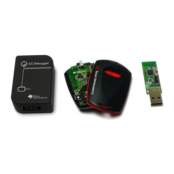
SWRU270C 2. Introduction Thank you for purchasing a Texas Instruments (TI) Bluetooth® low energy (BLE) Mini Development Kit. The purpose of this document is to give an overview of the hardware and software included in the CC2540 Mini Development Kit (CC2540DK-MINI) and the CC2541 Mini Development Kit (CC2541DK-MINI). -
Page 5: System Requirements
CC Debugger and the USB Dongle simultaneously. IAR Embedded Workbench for 8051 development environment is required in order to make changes to the keyfob software. More information on IAR can be found in the Texas Instruments Bluetooth® Low Energy Software Developer’s Guide [1]. -
Page 6: Getting Started
Figure 4 PC, Install Driver On the next screen, click the checkbox labeled “Include this location in the search:”, and click the “Browse” button. Select the following directory (assuming the default installation path was used): C:\Texas Instruments\BLE-CC254x-1.3\Accessories\Drivers Page 6 of 38... -
Page 7: Determining The Com Port
SWRU270C Figure 5 PC, Select Driver Click the “Next” button. This should install the driver. It will take a few seconds for the file to load. If the installation was successful, you should see the screen to the below. Click the “Finish” button to complete the installation. - Page 8 SWRU270C Figure 8 Win7 PC, Finding Device Manager A list of all hardware devices should appear. Under the section “Ports (COM & LPT)”, the device “TI CC2540 Low-Power RF to USB CDC Serial Port” should appear. Next to the name should be the port number (for example, the CC2540USB Dongle uses COM8 in Figure 9).
-
Page 9: Using Btool
4.1 Starting the Application To start the application go into your programs by choosing Start > Programs > Texas Instruments > BLE- CC254x-1.3 > BTool. On Start-up you should be able to set the Serial Port Settings. Set the “Port” value to the COM port earlier noted in Section 3.2. -
Page 10: Creating Able Connection Between Usb Dongle And Keyfob
SWRU270C Device Information Message Log Device Control Figure 11 BTool, Overview 4.2 Creating a BLE Connection between USB Dongle and Keyfob At this point the USB Dongle (central) is ready to discover other BLE devices that are advertising. The keyfob should be preloaded with the KeyFobDemo application. The full project and application source code files for KeyFobDemo is included in the BLE software development kit. -
Page 11: Scanning For Devices
SWRU270C 4.2.2 Scanning for Devices In BTool, Press the “Scan” button under the “Discover / Connect” tab, as shown in Figure 13. Figure 13 BTool, Scan for Devices The USB Dongle will begin search for other BLE devices. As devices are found, the log on the left side of the screen will display the devices discovered. -
Page 12: Selecting Connection Parameters
SWRU270C Figure 14 BTool, Slave Address 4.2.3 Selecting Connection Parameters Before establishing a connection, you can set up the desired connection parameters. The default values of 100ms connection interval, 0 slave latency, and 20s supervision timeout should serve as a good starting point;... - Page 13 SWRU270C Figure 16 BTool, Establish Connection If the keyfob is still in discoverable mode, a connection should be established (if more than 30 seconds have passed since the device was previously made discoverable, press the right button on the keyfob once again).
-
Page 14: Keyfobdemo Profiles
The KeyFobDemo software contains several GATT service profiles (More information on the KeyFobDemo can be found in the Texas Instruments BLE Sample Applications Guide [5]). GATT services contain data values known as “characteristic values”. All application data that is being sent or received in Bluetooth low energy must be contained within characteristic value. -
Page 15: Writing A Characteristic Value
SWRU270C An attribute protocol Read Request packet gets sent over the air from the dongle to the keyfob, and an attribute protocol Read Response packet gets sent back from the keyfob to the dongle. The new value is displayed in the “Value” box, and “Success” is displayed in the “Status” box. This value should match the value that was written in the previous step. -
Page 16: Using The Proximity Profile
SWRU270C 4.4 Using the Proximity Profile The Proximity profile is defined for a usage where an alert may be triggered on certain connection events, for example when the connection is, or about to be, dropped. Figure 19 Proximity Profile, Attribute Table The Proximity profile includes three services: ... -
Page 17: Activate Immediate Alert
SWRU270C An attribute protocol Write Request packet gets sent over the air from the dongle to the keyfob, and an attribute protocol Write Response packet gets sent back from the keyfob to the dongle. The status box will display “Success”, indicating that the write was successful. By default, the link does not timeout until 20 seconds have gone by without receiving a packet. - Page 18 SWRU270C = -6dBm Figure 22 Proximity Profile, TX Power The output power can be toggled (0dBm and -6dBm) by pressing the left button. Page 18 of 38...
-
Page 19: Using The Battery Service
SWRU270C 4.5 Using the Battery Service The Battery Service exposes the Battery Level of the coin cell battery on the keyfob. Figure 23 Battery Service, Attribute Table 4.5.1 Read the Battery Level They KeyFob used an ADC to read remaining battery level. The battery profile allows for a peer device (such as BTool) to read the percentage of battery remaining on the keyfob by reading the value of <BATTERY_LEVEL_UUID>... - Page 20 SWRU270C Figure 25 Battery Service, Enable Notification Notification of the battery level-state is handled inside the battery service and if the battery level has dropped since the previous measurement, a notification is sent as seen in Figure 26. = 53 % = 52 % Figure 26 BTool Log, Battery Service Notification Page 20 of 38...
-
Page 21: Using The Accelerometer Service
SWRU270C 4.6 Using the Accelerometer Service The keyfob uses SPI to interface to a 3 axis accelerometer on the keyfob. Note that accelerometer sensor can be of different vendors depending on the board revision. For example: CC2540 Keyfob v1.1 uses CMA3000d ... -
Page 22: Enable Accelerometer Notifications
SWRU270C Figure 28 Accelerometer Service, Enable Accelerometer 4.6.2 Enable Accelerometer Notifications Once the accelerometer is enabled, each axis can be configured to send notifications by writing “01 00” to the characteristic configuration for each axis < GATT_CLIENT_CHAR_CFG_UUID>. In addition, the values can be read directly by reading <ACCEL_X_UUID>, <ACCEL_Y_UUID>... -
Page 23: Using The Simple Keys Gatt Profile
Texas Instruments for use with the CC254XDK-MINI development kit. As the Bluetooth SIG begins to approve specifications for different service profiles, Texas Instruments plans to release updates to the BLE software development kit with source code conforming to the specifications. -
Page 24: Using Ble Security
SWRU270C 4.8 Using BLE Security BTool also includes the ability to make use of security features in BLE, including encryption, authentication, and bonding. 4.8.1 Encrypting the Connection To encrypt the link, the pairing process must be initiated. Click on the “Pairing / Bonding” tab in BTool. In the “Initiate Pairing”... -
Page 25: Using Bonding And Long-Term Keys
SWRU270C 34. Note that if you do not send the passkey within 30 seconds after receiving the pairing response message, the pairing process will fail, and you will need to re-send the pairing request. Figure 34 BTool, Sending Passkey When pairing is successfully completed, you will see a “GAP_AuthenticationComplete” event in the log window, with a “Success”... - Page 26 KeyFobDemo does not have a file system, it is simply storing the data in the nonvolatile memory of the CC2540/41. More information on the bond manager can be found in the Texas Instruments Bluetooth® Low Energy Software Developer’s Guide [3].
- Page 27 SWRU270C At a later time, re-connect with the keyfob following the procedure in section 4.2. Once connected, you will notice that the simple keys notifications are no longer enabled. This is because the Simple Keys profile will always reset the value of the client characteristic configuration descriptor back to “00:00” if a connection is terminated or if the device resets.
-
Page 28: Additional Sample Applications
Glucose Sensor – with simulated measurements SimpleBLEPeripheral - with proprietary profile which implements all various types of permissions More information on these projects can be found in the Texas Instruments BLE Sample Applications Guide [5]. Page 28 of 38... -
Page 29: Programming / Debugging The Cc2540 Or Cc2541
USB Dongle as well as the keyfob. This section details the hardware setup when using the CC Debugger, as well as information on using SmartRF Flash Programmer. Information on using IAR Embedded Workbench for debugging can be found in the Texas Instruments Bluetooth® Low Energy Software Developer’s Guide [3]. - Page 30 SWRU270C Figure 42 CC Debugger Interface Once the CC Debugger is set up with the status indicator LED showing green, you are ready to either read or write a hex file from the board, or to start debugging a project using IAR Embedded Workbench. Power Savings Tip: Do not leave the CC Debugger connected to the keyfob for and extended period of time with the battery in the keyfob.
-
Page 31: Hardware Setup For Usb Dongle
SWRU270C 5.2 Hardware Setup for USB Dongle The setup process for flashing the USB Dongle is very similar to the process when flashing the keyfob. First, plug the USB Dongle into a PC USB port (or a USB hub), as shown in Figure 44. Figure 44 CC2540 USB Dongle Connect the CC Debugger to the USB Dongle as shown below. - Page 32 SWRU270C Figure 46 CC Debugger Interface Once the CC Debugger status LED is showing green, as shown in Figure 46, you are ready to use IAR to debug or to read or write a hex file from/to the USB Dongle. Page 32 of 38...
-
Page 33: Using Smartrf Flash Programmer Software
1.12.6), which is available at the following URL: http://www.ti.com/tool/flash-programmer To start the application go into your programs by choosing Start > All Programs > Texas Instruments > SmartRF Flash Programmer > SmartRF Flash Programmer. The program start-up screen is shown in Figure Figure 47 Flash Programmer Note. -
Page 34: Reading Or Writing The Cc2540/41 Device Address
SWRU270C 5.3.2 Reading or Writing the CC2540/41 Device Address Every CC2540/41 device comes pre-programmed with a unique 48-bit IEEE address. This is referred to as the device’s “primary address”, and cannot be changed. It is also possible to set a “secondary address” on a device, which will override the primary address upon power-up. -
Page 35: Smartrf™ Packet Sniffer
SWRU270C 6. SmartRF™ Packet Sniffer The SmartRF™ Packet Sniffer is a PC software application used to display and store RF packets captured with a listening RF hardware node. Various RF protocols are supported, included Bluetooth low energy. The Packet Sniffer filters and decodes packets and displays them in a convenient way, with options for filtering and storage to a binary file format. -
Page 36: General Information
SWRU270C 7. General Information 7.1 Document History Revision Date Description/Changes SWRU270 (1.0) 2010-10-08 Initial release SWRU270A (1.0.1) 2010-11-29 Added information about packet sniffer and KeyFobDemo application SWRU270B (1.1) 2011-07-13 Updated with information from BLEv1.1 software release Updated with information on CC2541DK-MINI, now based on KeyFobDemo from SWRU270C (1.2) 2012-12-28 BLEv1.3. -
Page 37: Appendix
SWRU270C Appendix Page 37 of 38... - Page 38 SWRU270C Page 38 of 38...
- Page 39 Any exceptions to this are strictly prohibited and unauthorized by Texas Instruments unless user has obtained appropriate experimental/development licenses from local regulatory authorities, which is responsibility of user including its acceptable authorization.
- Page 40 FCC Interference Statement for Class B EVM devices This equipment has been tested and found to comply with the limits for a Class B digital device, pursuant to part 15 of the FCC Rules. These limits are designed to provide reasonable protection against harmful interference in a residential installation. This equipment generates, uses and can radiate radio frequency energy and, if not installed and used in accordance with the instructions, may cause harmful interference to radio communications.
- Page 41 Also, please do not transfer this product, unless you give the same notice above to the transferee. Please note that if you could not follow the instructions above, you will be subject to penalties of Radio Law of Japan. Texas Instruments Japan Limited (address) 24-1, Nishi-Shinjuku 6 chome, Shinjuku-ku, Tokyo, Japan http://www.tij.co.jp...
- Page 42 FDA Class III or similar classification, then you must specifically notify TI of such intent and enter into a separate Assurance and Indemnity Agreement. Mailing Address: Texas Instruments, Post Office Box 655303, Dallas, Texas 75265 Copyright © 2012, Texas Instruments Incorporated...
- Page 43 IMPORTANT NOTICE Texas Instruments Incorporated and its subsidiaries (TI) reserve the right to make corrections, enhancements, improvements and other changes to its semiconductor products and services per JESD46, latest issue, and to discontinue any product or service per JESD48, latest issue.
- Page 44 Mouser Electronics Authorized Distributor Click to View Pricing, Inventory, Delivery & Lifecycle Information: Texas Instruments CC2541DK-MINI...
Need help?
Do you have a question about the CC2540DK-MINI and is the answer not in the manual?
Questions and answers