Garmin REACTOR 40 KICKER Installation Instructions Manual
Hide thumbs
Also See for REACTOR 40 KICKER:
- Configuration manual (6 pages) ,
- Configuration manual (9 pages)
Table of Contents
Advertisement
Quick Links
REACTOR
40 KICKER
™
INSTALLATION INSTRUCTIONS
Important Safety Information
WARNING
See the Important Safety and Product Information guide in the product box for product warnings and other
important information.
You are responsible for the safe and prudent operation of your vessel. The autopilot is a tool that enhances your
capability to operate your boat. It does not relieve you of the responsibility of safely operating your boat. Avoid
navigational hazards and never leave the helm unattended.
Always be prepared to promptly regain manual control of your boat.
If your motor features a kill switch, you should know how to operate it in case of an emergency. If your motor
does not feature a kill switch, you should install one before installing the autopilot system.
Learn to operate the autopilot on calm and hazard-free open water.
Use caution when operating the autopilot near hazards in the water, such as docks, pilings, and other boats.
CAUTION
When in use, beware of hot surfaces on the heat-sink, motor, and solenoid components.
When in use, beware the risk of entrapment or pinching from moving parts.
Failure to install and maintain this equipment in accordance with these instructions could result in damage or
injury.
Installation Preparation
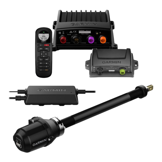
The autopilot system consists of multiple components. You should familiarize yourself with all of the
component mounting and connection considerations before beginning installation. You must know how the
components operate together in order to correctly plan the installation on your boat.
You can consult the layout diagrams to help understand the mounting and connection considerations.
You should lay out all of the components on the boat as you plan the installation to make sure your cables will
reach each component. If needed, extension cables (sold separately) for various components are available from
your Garmin
®
dealer or from www.garmin.com.
You should record the serial number of each component for registration and warranty purposes.
January 2022
GUID-EF2BAA44-88E5-4854-882C-9A77AB104F05 v3
Advertisement
Table of Contents

Related Manuals for Garmin REACTOR 40 KICKER


Summary of Contents for Garmin REACTOR 40 KICKER
- Page 1 If needed, extension cables (sold separately) for various components are available from your Garmin ® dealer or from www.garmin.com. You should record the serial number of each component for registration and warranty purposes. January 2022 GUID-EF2BAA44-88E5-4854-882C-9A77AB104F05 v3...
-
Page 2: Tools And Supplies Needed
Tools and Supplies Needed • Safety glasses • Drill and drill bits • Wrenches • 90 mm (3.5 in.) hole saw or a rotary cutting tool (for installing an optional helm control) • Wire cutters/strippers • Phillips and flat screwdrivers •... -
Page 3: Power And Data Layout
You must connect the NMEA 2000 power cable to a 9 to 16 Vdc power source. You must connect the helm control or compatible Garmin chartplotter and the CCU to a NMEA 2000 network using the included T-connectors... -
Page 4: Mounting And Connection Considerations
CCU Mounting and Connection Considerations • The CCU is the primary sensor of the Reactor 40 Kicker autopilot system. For best performance, observe these considerations when selecting a mounting location. ◦ A handheld compass should be used to test for magnetic interference in the area where the CCU is to be mounted(Testing a Location for Magnetic Interference, page ◦... - Page 5 Finding the Best Mounting Location 1 Create a list of all suitable mounting locations for the CCU. Suitable mounting locations should not be within 60 cm (2 ft.) of the following: • Iron • Magnets • High-current wires • Intermittently-running pumps, such as head pumps and live well pumps A large magnet, such as a subwoofer-speaker magnet, should be no closer than 1.5 m (5 ft.) to any of the mounting locations.
-
Page 6: Installation Procedures
A dedicated helm control is not included in all autopilot packages. If you install the autopilot without a dedicated helm control, the autopilot CCU must be connected to the same NMEA 2000 network as a compatible Garmin chartplotter to configure and control the autopilot system. -
Page 7: Mounting The Ccu
Mounting the CCU 1 Determine the mounting location. 2 Using the CCU as a template, mark the two pilot hole locations on the mounting surface. 3 Using a 3 mm ( in.) bit, drill the pilot holes. 4 Use the included screws to attach the CCU to the mounting surface. NOTE: If you use mounting hardware other than the provided screws, the hardware must be quality stainless or brass material to avoid magnetic interference with the CCU. - Page 8 Additional Grounding Consideration This device should not need additional chassis grounding in most installation situations. If you experience interference, you can use the grounding screw on the housing to connect the device to the water ground of the boat to help avoid the interference.
- Page 9 Power Cable Extensions If necessary, you can extend the power cable using the appropriate wire gauge for the length of the extension. Item Description Fuse Battery 9 ft. (2.7 m) no extension Item Description Splice 10 AWG (5.26 mm²) extension wire Fuse 8 in.
- Page 10 Item Description Splice 8 AWG (8.36 mm²) extension wire Fuse 8 in. (20.3 cm) Battery 8 in. (20.3 cm) Up to 23 ft. (7 m) Item Description Splice 6 AWG (13.29 mm²) extension wire Fuse 8 in. (20.3 cm) Battery 8 in.
- Page 11 NOTE: Some kits contain a stainless steel tilt tube, or you can purchase a stainless steel tilt tube from your local marine dealer or from www.garmin.com. 3 If necessary, remove the caps on both ends of the tilt tube.
- Page 12 Installing the Steering Actuator in the Tilt Tube 1 Apply white lithium grease to the push rod on the steering actuator. 2 Starting from either side, feed the steering actuator into the tilt tube. 3 Screw the steering actuator onto the end of the tilt tube. 4 Rotate the steering actuator until the connector is facing the best direction for your installation.
- Page 13 Installing the Kicker Motor Bracket and Steering Linkage After you have installed the steering actuator in the tilt tube, you must install one of the provided motor brackets on the Kicker motor tiller arm and connect it to the steering actuator using the a linkage arm. 1 Review the table to determine which type of bracket your motor requires.
- Page 14 Installing the Right-Angle Bracket and Linkage Arm Because Kicker motors create excessive vibration under use, you must apply a humidity-cured ethyl-based thread-locking compound, such as LOCTITE 435 to the threads on the motor bracket, the bushing, and the nut ® in this assembly.
- Page 15 Installing the Flat Bracket and Linkage Arm You should use the flat bracket when installing the steering actuator on kicker motors with bolts or mounting holes on the underside of the tiller arm, such as Yamaha motors. 1 Locate the mounting holes or bolts on the underside of the tiller arm on the kicker motor that align with the holes on the bracket.
-
Page 16: Connecting The Ccu
Connecting the Linkage Arm to the Steering Actuator After you connect the linkage arm to your kicker motor tiller arm using the appropriate bracket, you must connect it to the steering actuator. 1 Screw the linkage pin into the end of the steering actuator rod, and secure it with the lock nut 2 Referring to the diagram, install the spacer , washers , and linkage arm... -
Page 17: Nmea 2000 And The Autopilot Components
A dedicated helm control is not included in all autopilot packages. If you install the autopilot without a dedicated helm control, the autopilot CCU must be connected to the same NMEA 2000 network as a compatible Garmin chartplotter to configure and control the autopilot system. -
Page 18: Connecting Optional Nmea 2000 Devices To The Autopilot System
A dedicated helm control is not included in all autopilot packages. If you install the autopilot without a dedicated helm control, the autopilot CCU must be connected to the same NMEA 2000 network as a compatible Garmin chartplotter to configure and control the autopilot system. -
Page 19: Maintenance
6 Using solvent and a rag, clean the push rod on the steering actuator. 7 Apply white lithium grease to the push rod, and re-install the steering actuator. Replacement Parts Replacement parts are available for this autopilot system. Contact your Garmin dealer or go to www.garmin.com for more information. -
Page 20: Nmea 0183 Connection Diagrams
NMEA 0183 devices according to these diagrams. If you install the autopilot without a helm control, all NMEA devices you plan to use with the autopilot system must be connected to a compatible Garmin chartplotter on the same NMEA 2000 network as the CCU. See the installation instructions provided with your chartplotter for NMEA 0183 connection information. - Page 21 Two-Way NMEA 0183 Communication NMEA 2000 network (provides power to the helm control) 12 Vdc power source Helm control NMEA 0183 compatible device Wire Helm Control Wire Color — Function NMEA 0183 Compatible Device Wire Function Power NMEA 0183 ground Blue —...
- Page 22 Only One Receiving Wire If your NMEA 0183 compatible device has only one receiving wire (Rx), you must connect it to the blue wire (Tx/A) from the helm control, and leave the white wire (Tx/B) from the helm control unconnected. NMEA 2000 network (provides power to the helm control) 12 Vdc power source Helm control...
- Page 23 Only One Transmitting Wire If your NMEA 0183 compatible device has only one transmitting wire (Tx), it must be connected to the brown wire (Rx/A) from the helm control, and the green wire (Rx/B) from the helm control must be connected to NMEA 0183 ground.
- Page 24 From 11.5 to 30 Vdc Input voltage Fuse 40 A, blade-type Main power usage 1 A (not including the drive actuator) The device withstands incidental exposure to water of up to 1 m for up to 30 min. For more information, go to www.garmin.com/waterrating.
-
Page 25: Nmea 2000 Pgn Information
NMEA 2000 PGN Information Type Description Transmit and receive 059392 ISO acknowledgment 059904 ISO request 060928 ISO address claim 126208 NMEA: Command/Request/Acknowledge group function 126464 Transmit/Receive PGN list group function 126996 Product information 127257 Transmit/Receive attitude data 127251 Transmit/Receive rate of turn Transmit only 127250 Vessel heading... - Page 26 Helm Control Type Description Transmit and receive 059392 ISO acknowledgment 059904 ISO request 060928 ISO address claim 126208 NMEA: Command/Request/Acknowledge group function 126464 Transmit/Receive PGN list group function 126996 Product information Transmit only 128259 Water speed 129025 Position: Rapid update 129026 COG &...
-
Page 27: Nmea 0183 Information
NMEA 0183 Information When connected to optional NMEA 0183 compatible devices, the autopilot uses the following NMEA 0183 sentences. Type Sentence Transmit Receive grme... -
Page 28: Error And Warning Messages
© 2019 Garmin Ltd. or its subsidiaries Garmin ® and the Garmin logo are trademarks of Garmin Ltd. or its subsidiaries, registered in the USA and other countries. Reactor is a trademark of Garmin Ltd. or its ™ subsidiaries. This trademark may not be used without the express permission of Garmin.
Need help?
Do you have a question about the REACTOR 40 KICKER and is the answer not in the manual?
Questions and answers