Table of Contents
Advertisement
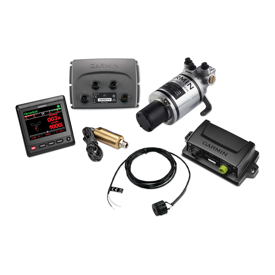
REACTOR™ 40 COMPACT
HYDRAULIC
Installation Instructions
Important Safety Information
See the Important Safety and Product Information guide in the
product box for product warnings and other important
information.
You are responsible for the safe and prudent operation of your
vessel. The autopilot is a tool that enhances your capability to
operate your boat. It does not relieve you of the responsibility of
safely operating your boat. Avoid navigational hazards and
never leave the helm unattended.
Always be prepared to promptly regain manual control of your
boat.
Learn to operate the autopilot on calm and hazard-free open
water.
Use caution when operating the autopilot near hazards in the
water, such as docks, pilings, and other boats.
When in use, beware of hot motor and solenoid components
and the risk of entrapment from moving parts.
Failure to install and maintain this equipment in accordance with
these instructions could result in damage or injury.
To avoid damage to your boat, the autopilot system should be
installed by a qualified marine installer. Specific knowledge of
hydraulic steering componentry and marine electrical systems is
required for proper installation.
Registering Your Device
Help us better support you by completing our online registration
today. Keep the original sales receipt, or a photocopy, in a safe
place.
1
Go to
garmin.com/express
2
Sign in to your Garmin
®
Installation Preparation
The autopilot system consists of multiple components. You
should familiarize yourself with all of the component mounting
and connection considerations before beginning installation. You
must know how the components operate together in order to
correctly plan the installation on your boat.
You can consult the layout diagrams
page
2) to help understand the mounting and connection
considerations.
You should lay out all of the components on the boat as you
plan the installation to make sure your cables will reach each
component. If needed, extension cables (sold separately) for
various components are available from your Garmin dealer or
from www.garmin.com.
You should record the serial number of each component for
registration and warranty purposes.
Tools Needed
• Safety glasses
• Drill and drill bits
• Wrenches
• 90 mm (3.5 in.) hole saw or a rotary cutting tool (for installing
an optional helm control)
WARNING
CAUTION
NOTICE
.
account.
(Power and Data Layout,
• Wire cutters/strippers
• Phillips and flat screwdrivers
• Cable ties
• Single Pole Single Throw (SPST) switch (to use as an
autopilot bypass when not installing the Shadow Drive
valve)
• Waterproof wire connectors (wire nuts) or heat-shrink tubing
and a heat gun
• Marine sealant
• Marine corrosion inhibitor spray
• Portable or handheld compass (to test for magnetic
interference)
• Hydraulic hose with machine-crimped or field-replaceable
fittings that have a minimum rating of 1000 psi
• Hydraulic T-fittings
• Hydraulic fluid
• Thread sealant
• Hydraulic bleeding equipment
NOTE: Mounting screws are provided for the main components
of the autopilot system. If the provided screws are not
appropriate for the mounting surface, you must provide the
correct types of screws.
Mounting and Connection Considerations
The autopilot components connect to each other and to power
using the included cables. Ensure that the correct cables reach
each component and that each component is in an acceptable
location before mounting or wiring any components.
CCU Mounting and Connection Considerations
• The CCU is the primary sensor of the Reactor 40 Compact
Hydraulic autopilot system. For best performance, observe
these considerations when selecting a mounting location.
◦ A handheld compass should be used to test for magnetic
interference in the area where the CCU is to be
mounted(Testing a Location for Magnetic Interference,
page
2).
◦ The CCU should be mounted on a rigid surface for best
performance.
• Mounting screws are provided with the CCU. If you use
mounting hardware other than the provided screws, the
hardware must be quality stainless or brass material to avoid
magnetic interference with the CCU.
Test any mounting hardware with a handheld compass to
make sure no magnetic fields are present in the hardware.
• The CCU cable connects the CCU to the ECU and is 5 m
(16 ft.) long.
◦ If the CCU cannot be mounted within 5 m (16 ft.) of the
ECU, extension cables are available from your local
Garmin dealer or at www.garmin.com.
◦ This cable must not be cut.
Finding the Best Mounting Location
1
Create a list of all suitable mounting locations for the CCU.
Suitable mounting locations should not be within 60 cm (2 ft.)
of the following:
• Iron
• Magnets
• High-current wires
• Intermittently-running pumps, such as head pumps and
live well pumps
A large magnet, such as a subwoofer-speaker magnet,
should be no closer than 1.5 m (5 ft.) to any of the mounting
locations.
™
October 2017
190-02316-02_0A
Advertisement
Table of Contents

Subscribe to Our Youtube Channel
Related Manuals for Garmin REACTOR 40 COMPACT HYDRAULIC


Summary of Contents for Garmin REACTOR 40 COMPACT HYDRAULIC
-
Page 1: Installation Instructions
If needed, extension cables (sold separately) for Suitable mounting locations should not be within 60 cm (2 ft.) various components are available from your Garmin dealer or of the following: from www.garmin.com. - Page 2 Locate the center of rotation of the boat, and measure the • The Shadow Drive should be mounted lower than the lowest distance between the center of rotation and each of the helm, but higher than the pump. suitable mounting locations you listed in step 1. •...
- Page 3 Important Considerations NMEA 2000 You must connect the helm control or network compatible Garmin chartplotter and the CCU to Helm control A dedicated helm control is not included in all a NMEA 2000 network using the included T- autopilot packages. If you install the autopilot...
- Page 4 (Building a Basic NMEA hydraulic lines to the pump. 2000 Network for the Autopilot System, • To allow for easy pump disabling and removal, Garmin page recommends installing shut-off valves in the hydraulic lines between the pump manifold and T-connectors.
-
Page 5: Installation Procedures
If you install the autopilot without a dedicated helm control, the autopilot CCU must be connected to the same NMEA 2000 network as a compatible Garmin chartplotter to configure and control the autopilot system. Detailed mounting instructions are included in the helm control box. - Page 6 Route the orange and blue wires from the bare-wire portion control, the autopilot CCU must be connected to the same of the CCU cable to the location where you plan to install the NMEA 2000 network as a compatible Garmin chartplotter to alarm (Installing the Alarm, page...
- Page 7 CCU must be connected to the same the existing network and the Garmin devices. NMEA 2000 network as a compatible Garmin chartplotter to configure and control the autopilot system. You can connect the CCU and the optional helm control through an existing NMEA 2000 network.
- Page 8 NMEA 0183 data cable. You can connect one NMEA 0183 Before you bleed the hydraulic system, you should verify that all device to the internal RX port to input data to this Garmin hose connections are complete and fully tightened.
-
Page 9: Specifications
(Rx/B) from the helm control *The device withstands incidental exposure to water of up to 1 m for up must be connected to NMEA 0183 ground. to 30 min. For more information, go to www.garmin.com/waterrating. Specification Measurement Dimensions (W ×... -
Page 10: Error And Warning Messages
NMEA 0183 sentences. Help us better support you by completing our online registration today. Keep the original sales receipt, or a photocopy, in a safe Type Sentence place. Transmit Go to garmin.com/express Receive Sign in to your Garmin account. - Page 11 Shadow Drive are trademarks ™ ™ of Garmin Ltd. or its subsidiaries. These trademarks may not be used without the express permission of Garmin. NMEA , NMEA 2000 , and the NMEA 2000 logo are trademarks of the National Marine ®...
Need help?
Do you have a question about the REACTOR 40 COMPACT HYDRAULIC and is the answer not in the manual?
Questions and answers