Table of Contents
Advertisement
Quick Links
COMPACT REACTOR
40 HYDRAULIC
™
INSTALLATION INSTRUCTIONS
Important Safety Information
WARNING
See the Important Safety and Product Information guide in the product box for product warnings and other
important information.
To avoid possible personal injury and damage to your boat, the autopilot system should be installed by a
qualified marine installer. Specific knowledge of marine steering and electrical systems is required for proper
installation.
You are responsible for the safe and prudent operation of your vessel. The autopilot is a tool that enhances your
capability to operate your boat. It does not relieve you of the responsibility of safely operating your boat. Avoid
navigational hazards and never leave the helm unattended.
Always be prepared to promptly regain manual control of your boat.
Learn to operate the autopilot on calm and hazard-free open water.
Use caution when operating the autopilot near hazards in the water, such as docks, pilings, and other boats.
CAUTION
Failure to install and maintain this equipment in accordance with these instructions could result in damage or
injury.
When in use, beware of hot surfaces on the heat-sink, motor, and solenoid components.
When in use, beware the risk of entrapment or pinching from moving parts.
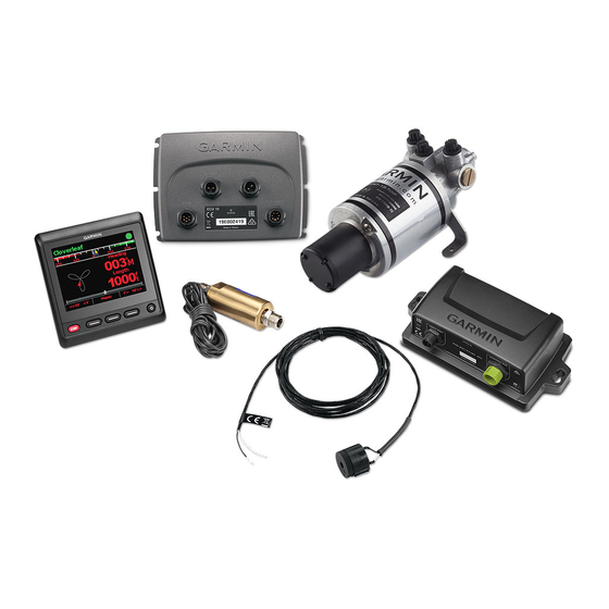
Installation Preparation
The autopilot system consists of multiple components. You should familiarize yourself with all of the
component mounting and connection considerations before beginning installation. You must know how the
components operate together in order to correctly plan the installation on your boat.
You can consult the layout diagrams to help understand the mounting and connection considerations.
You should lay out all of the components on the boat as you plan the installation to make sure your cables will
reach each component. If needed, extension cables (sold separately) for various components are available from
your Garmin
dealer or from garmin.com.
®
You should record the serial number of each component for registration and warranty purposes.
May 2022
GUID-E60BF24E-0510-46B3-8BEC-D55273E88F18 v3
Advertisement
Table of Contents

Subscribe to Our Youtube Channel
Related Manuals for Garmin COMPACT REACTOR 40


Summary of Contents for Garmin COMPACT REACTOR 40
- Page 1 You should lay out all of the components on the boat as you plan the installation to make sure your cables will reach each component. If needed, extension cables (sold separately) for various components are available from your Garmin dealer or from garmin.com. ® You should record the serial number of each component for registration and warranty purposes.
-
Page 2: Tools And Supplies Needed
Tools and Supplies Needed • Safety glasses • Drill and drill bits • Wrenches • Jigsaw or a rotary cutting tool (for installing an optional helm control) • Wire cutters/strippers • Phillips and flat screwdrivers • Cable ties • Solder and water-tight heat shrink tubing or water-tight, heat-shrink, butt-splice connectors •... - Page 4 You must connect the NMEA 2000 power cable to a 9 to 16 Vdc power source. You must connect the helm control or compatible Garmin chartplotter and the CCU to a NMEA 2000 network using the included T-connectors (NMEA 2000 Connection...
-
Page 5: Component Layout
A dedicated helm control is not included in all autopilot packages. If you install the autopilot without a dedicated helm control, the autopilot CCU must be connected to Helm control the same NMEA 2000 network as a compatible Garmin chartplotter to configure and control the autopilot system. Pump You must connect the ECU to a 12 to 24 Vdc power source. - Page 6 CCU must be connected to Helm control the same NMEA 2000 network as a compatible Garmin chartplotter to configure and control the autopilot system. You must connect the ECU to a 12 to 24 Vdc power source. To extend this cable, use 12 to 24 Vdc...
- Page 7 CCU Mounting and Connection Considerations • The CCU is the primary sensor of the Compact Reactor 40 Hydraulic autopilot system. For best performance, observe these considerations when selecting a mounting location. ◦ A handheld compass should be used to test for magnetic interference in the area where the CCU is to be mounted(Testing a Location for Magnetic Interference, page 7).
- Page 8 ECU Mounting and Connection Considerations • The ECU can be mounted on a flat surface, facing any direction. • Mounting screws are included with the ECU, but you may need to provide different screws if the supplied screws are not suitable for the mounting surface. •...
-
Page 9: Important Considerations
If the steering system in your boat does not match any of the hydraulic layouts in this manual and you are unsure how to install the pump, contact Garmin Product Support. Before you start the pump installation, identify the type of hydraulic steering system in your boat. Each boat is different, and you must consider certain aspects of the existing hydraulic layout before deciding where to mount the pump. - Page 10 Shadow Drive sensor Starboard line Return line Shut-off valves Port line Pump Helm Steering cylinder Dual-Helm Layout...
-
Page 11: Installation Procedures
A dedicated helm control is not included in all autopilot packages. If you install the autopilot without a dedicated helm control, the autopilot CCU must be connected to the same NMEA 2000 network as a compatible Garmin chartplotter to configure and control the autopilot system. -
Page 12: Ecu Installation
ECU Installation Mounting the ECU Before you can mount the ECU, you must select a location and determine the correct mounting hardware (ECU Mounting and Connection Considerations, page 8). 1 Hold the ECU in the intended mounting location and mark the locations of the mounting holes on the mounting surface, using the ECU as a template. - Page 13 Item Description Splice 10 AWG (5.26 mm²) extension wire Fuse 8 in. (20.3 cm) Battery 8 in. (20.3 cm) Up to 15 ft. (4.6 m)
- Page 14 Item Description Splice 8 AWG (8.36 mm²) extension wire Fuse 8 in. (20.3 cm) Battery 8 in. (20.3 cm) Up to 23 ft. (7 m) Item Description Splice 6 AWG (13.29 mm²) extension wire Fuse 8 in. (20.3 cm) Battery 8 in. (20.3 cm) Up to 36 ft. (11 m)
-
Page 15: Pump Installation
Pump Installation Mounting the Pump Before you can mount the pump, you must select a location (Pump Mounting Considerations, page 8) and determine the correct mounting hardware (Tools and Supplies Needed, page 2). 1 Hold the pump in the intended mounting location and mark the locations of the mounting holes on the mounting surface, using the pump as a template. - Page 16 A dedicated helm control is not included in all autopilot packages. If you install the autopilot without a dedicated helm control, the autopilot CCU must be connected to the same NMEA 2000 network as a compatible Garmin chartplotter to configure and control the autopilot system.
- Page 17 A dedicated helm control is not included in all autopilot packages. If you install the autopilot without a dedicated helm control, the autopilot CCU must be connected to the same NMEA 2000 network as a compatible Garmin chartplotter to configure and control the autopilot system.
- Page 18 A dedicated helm control is not included in all autopilot packages. If you install the autopilot without a dedicated helm control, the autopilot CCU must be connected to the same NMEA 2000 network as a compatible Garmin chartplotter to configure and control the autopilot system.
- Page 19 The autopilot must be configured and tuned to your boat dynamics. You can use the Dockside Wizard and the Sea Trial Wizard on the helm control or a compatible Garmin chartplotter to configure the autopilot. See the included configuration guide for more information on configuring the autopilot.
-
Page 20: Maintenance
Fully gasketed, high-impact plastic Water rating IEC 60529 IPX7* NMEA 2000 input voltage From 9 to 16 Vdc NMEA 2000 LEN 4 (200 mA) The device withstands incidental exposure to water of up to 1 m for up to 30 min. For more information, go to www.garmin.com/waterrating. - Page 21 2.4 oz. (68 g) Temperature range From 5°F to 140°F (from -15°C to 60°C) Cable length 10 ft. (3.0 m) The device withstands incidental exposure to water of up to 1 m for up to 30 min. For more information, go to www.garmin.com/waterrating.
-
Page 22: Nmea 2000 Pgn Information
Cross track error 129284 Navigation data 130306 Wind data Helm Control A dedicated helm control is not included in all autopilot packages. To view the PGN information for a helm control device, see the product owner's manual available for download at garmin.com/manuals/ghc50. -
Page 23: Error And Warning Messages
• In Europe, call +44 (0) 870 850 1241. © 2022 Garmin Ltd. or its subsidiaries Garmin ® and the Garmin logo are trademarks of Garmin Ltd. or its subsidiaries, registered in the USA and other countries. Reactor ™ and Shadow Drive ™... - Page 24 © 2022 Garmin Ltd. or its subsidiaries support.garmin.com...
Need help?
Do you have a question about the COMPACT REACTOR 40 and is the answer not in the manual?
Questions and answers