
Related Manuals for Cameron WHEATLEY 500 Series


Summary of Contents for Cameron WHEATLEY 500 Series
- Page 1 Document Number: TC003001-13 Revision: 02 WHEATLEY® Series 500 Swing Check Valve Installation, Operation, and Maintenance Manual...
-
Page 2: Table Of Contents
REASSEMBLY................................8 CONTACT INFORMATION ..............................9 All the information contained in this manual is the exclusive property of Cameron. Any reproduction or use of the calculations, drawings, photographs, procedures or instructions, either expressed or implied, is forbidden without the written permission of Cameron or its authorized agent. -
Page 3: Bill Of Materials
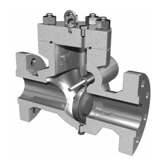
BILL OF MATERIALS FLOW Figure 1 - Integral Seat Swing Check Table 1 - Integral Seat Swing Check Parts List Item Description Bonnet O-Ring Stud Stud Eyebolt Cover Plug Bonnet Body Drain Clapper O-Ring Clapper TC-003001-13/ Rev 02... - Page 4 FLOW Figure 2 - Removable Seat Swing Check Table 2 - Removable Seat Swing Check Parts List Item Description Bonnet O-Ring Stud Stud Eyebolt Cover Plug Bonnet Body Removable Seat Seat O-Ring Retaining Ring Seat Face O-Ring Clapper TC-003001-13/ Rev 02...
-
Page 5: Scope
SCOPE The flanged swing check valve (Figure 1& Figure 2) features a hinged stainless steel clapper with an O-ring seal. The design allows the clapper to swing freely from the fully closed position to the fully opened position and back. Two NPT plugs secure the hinge pin in a hole drilled through the body. -
Page 6: Horizontal Installation
7. If the valve, in service, is exposed to hazards such as traffic, wind or earthquake loading, contact the factory, if it is necessary, to confirm that the valve design is suitable for the application. The factory requires a complete description of the hazard before making any recommendations. 8. -
Page 7: Vertical Installation
When installing the swing check valve in the horizontal position, install the valve with the arrow mark on the body pointing in the direction of flow and the bonnet side up. Flow through the valve (in the direction of the arrow mark) forces the clapper to lift fully. The clapper seals the valve when the flow is reversed. -
Page 8: Reassembly
Thoroughly clean the clapper/seat sealing surfaces. Inspect both the clapper and body/seat sealing surfaces for possible scoring marks or damage. The seating surfaces must be smooth. Inspect the bonnet O-ring seal for damage. Replace the O-ring if it is damaged. Generally the bonnet O-ring will last longer than the clapper O-ring. REASSEMBLY For the removable seat model, make sure the 2 O-rings are installed in the 2 grooves on the seat. -
Page 9: Contact Information
Table 4 - Recommended Number of Spare Parts Qty. of Valves Qty. of Minor Kits Qty. of Major Kits Qty. of Comprehensive Kits Table 5 - Repair Kit Contents Integral Seat Removable Seat Part Name Minor Major Minor Major Bonnet O-Ring Clapper O-Ring Seat O-Rings (Face &...
Need help?
Do you have a question about the WHEATLEY 500 Series and is the answer not in the manual?
Questions and answers