
Related Manuals for Cameron TK


Summary of Contents for Cameron TK
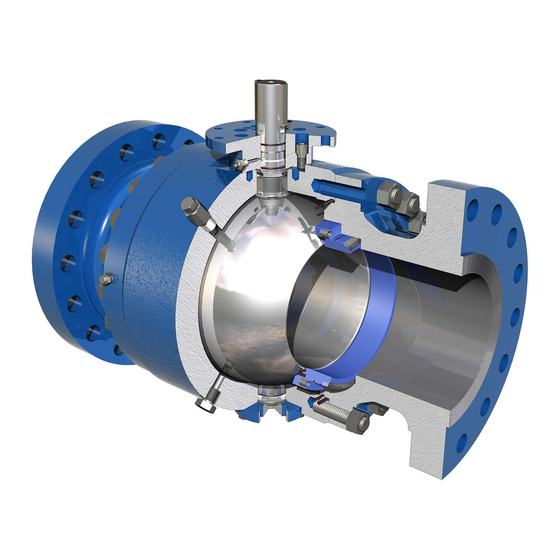
- Page 1 E N G I N E E R E D & P R O C E S S V A L V E S Installation, Operation and Maintenance Manual ® Hi-Integrity Trunnion Mounted Ball Valve ®...
-
Page 2: Table Of Contents
Scope ....................3 Bill of Materials ..................4 Figure 1 – TK Valve – Two piece Non-Trunnion Mounted Ball Valve..4 Figure 2 – TK Valve – Two piece Trunnion Mounted Ball Valve....6 Figure 3 – TK Valve – Three piece Trunnion Mounted Ball Valve.... 8 Nameplate Information ................. -
Page 3: Scope
E N G I N E E R E D & P R O C E S S V A L V E S SCOPE The TK Valve is designed and manufactured to provide trouble free service and a long service life. This manual provides the relevant information that is required for the successful operation of standard and fire safe (end entry) TK Valves. -
Page 4: Bill Of Materials
E N G I N E E R E D & P R O C E S S V A L V E S BILL OF MATERIALS Figure 1 – TK Valve – Two piece Non-Trunnion Mounted Ball Valve Installation, Operation and Maintenance Manual... - Page 5 4. Are only used on gear operated valves. Lever operated valves do not require a key. 5. Only used on trunnion mounted ball valves. See figure 2 for details. * Quantity may change depending on valve size. Installation, Operation and Maintenance Manual 01/2011 / IOM-TK-TMBV-01...
- Page 6 E N G I N E E R E D & P R O C E S S V A L V E S BILL OF MATERIALS Figure 2 – TK Valve – Two piece Trunnion Mounted Ball Valve Installation, Operation and Maintenance Manual...
- Page 7 3. On smaller two-piece trunnion and non-trunnion mounted valves coil springs are not used. 4. When coil springs are not used, the wave spring is then replaced with a Belleville spring. * Quantity may change depending on valve size. Installation, Operation and Maintenance Manual 01/2011 / IOM-TK-TMBV-01...
- Page 8 E N G I N E E R E D & P R O C E S S V A L V E S BILL OF MATERIALS Figure 3 – TK Valve – Three piece Trunnion Mounted Ball Valve Installation, Operation and Maintenance Manual...
- Page 9 3. Not included on all valve designs. Lifting lugs are used on 6” class 1500 & 2500 and 8” class 600 and up. * Quantity may change depending on valve size and class. Installation, Operation and Maintenance Manual 01/2011 / IOM-TK-TMBV-01...
-
Page 10: Nameplate Information
E N G I N E E R E D & P R O C E S S V A L V E S NAMEPLATE INFORMATION TK can provide either a non-monogram or monogram API-6D, API-6A, and/or a CE tag. All tags are securely placed onto the valve and will have the information below stamped in each section. -
Page 11: Storage
Valves left in storage for periods greater that three (3) years should be hydrostatically tested prior to installation. Valves left in storage for periods greater than six (6) years should be disassembled, cleaned and inspected for damage. All elastomeric seals should be replaced at that time. Installation, Operation and Maintenance Manual 01/2011 / IOM-TK-TMBV-01... -
Page 12: Installation
INSTALLATION Certified lifting devices that are rated for the valve weight should be used when lifting any TK Valves. For valve sizes 1.5” up to 4”, 6” class 150 thru 900, and 8” class 150 thru 300 the lifting points should be around the valve neck on either side. -
Page 13: Hydrostatic Testing
E N G I N E E R E D & P R O C E S S V A L V E S HYDROSTATIC TESTING All TK Valves are tested per API-6D or API-6A test requirements. Each valve is tested to a factory closure test at 100% of maximum operating pressure. Valves should not be used as closures for systems where the operating pressure exceeds these figures. -
Page 14: Mounting A Gear Box/Actuator
There should not be more than 1/16” of the ball radius exposed into the flow bore once the final setting has been made. Installation, Operation and Maintenance Manual 01/2011 / IOM-TK-TMBV-01... - Page 15 If further alignment is necessary screw the open stop screw in or out to readjust the ball travel. Replace indicator cap and tighten all fasteners. Handwheel Shaft Indicator Cap (Shown in Closed Position) Stud Holes Closed Stop Screw Open Stop Screw Installation, Operation and Maintenance Manual 01/2011 / IOM-TK-TMBV-01...
-
Page 16: Routine Maintenance
E N G I N E E R E D & P R O C E S S V A L V E S ROUTINE MAINTENANCE Lubrication of TK Valves is not necessary for all applications, and is not a requirement for the valve to seal pressure. In certain applications however, as in dry gas for example, lubrication twice yearly is recommended. -
Page 17: Seat Sealant
TK Valves are generally designed with auxiliary sealant fittings that are used to inject sealant directly to the ball sealing area. This is sometimes necessary in preventing damage to the seats by flushing debris away from the seats and in the event of a damaged seat caused by debris in the line. -
Page 18: Disassembly And Reassembly
Collect and retain seat springs. Two-Piece Trunnion Supported Remove bonnet and stem from valve. Remove trunnion flange. It is not necessary to separate the trunnion from the flange. Remove adapter. Remove ball from body cavity. Installation, Operation and Maintenance Manual 01/2011 / IOM-TK-TMBV-01... - Page 19 Stem and ball bushings, washers, and disc should be replaced if damaged or worn. O-rings should be replaced if broken, nicked, frayed, stretched, or swollen. If O-rings are dam- aged due to incompatible service conditions, consult with the nearest representative or the factory. Installation, Operation and Maintenance Manual 01/2011 / IOM-TK-TMBV-01...
-
Page 20: Reassembly
Ensure the ball is aligned with the stem bore and insert the stem. At this time the trunnion can be completely installed. Install the bonnet onto the body. Install the closure onto the body. Installation, Operation and Maintenance Manual 01/2011 / IOM-TK-TMBV-01... - Page 21 On lever operated valves, make sure of correct location of the stop socket head cap screw. Tighten all bolting on the assembled valve. Reinstall operator onto the valve. See “Mounting Gear Box and Actuator” in installation instructions. If available retest the valve to the appropriate specifications. Installation, Operation and Maintenance Manual 01/2011 / IOM-TK-TMBV-01...
-
Page 22: Troubleshooting
Inject seat sealant for temporary seal or replace Damaged seat face or seat O-ring seats Valve not fully closed Check that operator or limit-switches do not stop the rotation of ball prior to reaching the fully closed position. Installation, Operation and Maintenance Manual 01/2011 / IOM-TK-TMBV-01... - Page 23 E N G I N E E R E D & P R O C E S S V A L V E S Installation, Operation and Maintenance Manual 01/2011 / IOM-TK-TMBV-01...
- Page 24 E N G I N E E R E D & P R O C E S S V A L V E S VALVES & MEASUREMENT 3250 Briarpark Drive, Suite 300 Houston, TX 77042 USA Toll 800 323 9160 For the most current contact and location information go to: www.c-a-m.com Installation, Operation and Maintenance Manual 01/2011 / IOM-TK-TMBV-01...
Need help?
Do you have a question about the TK and is the answer not in the manual?
Questions and answers