
Related Manuals for Cameron WKM 370D6


Summary of Contents for Cameron WKM 370D6
- Page 1 Date: 4 March 2015 Document Number: TC-003001-30 Revision: Rev 01 WKM® 370D6 Ball Valve Installation, Operation, and Maintenance Manual...
- Page 2 All the information contained in this manual is the exclusive property of Cameron. Any reproduction or use of the calculations, drawings, photographs, procedures or instructions, either expressed or implied, is forbidden without the written permission of Cameron or its authorized agent.
-
Page 3: Table Of Contents
TABLE OF CONTENTS BILL OF MATERIALS ................................ 5 SCOPE .................................... 9 NAMEPLATE INFORMATION ............................10 STORAGE ..................................11 VALVES DELIVERED BY WKM ........................... 11 INSTALLATION AND OPERATION INSTRUCTIONS ......................11 BEFORE INSTALLATION SAFTEY INFORMATION ....................... 11 INSTALLATION ................................12 FIELD TESTING................................13 OPERATION ................................ - Page 4 File copies of this manual are maintained. Revisions and/or additions will be made as deemed necessary by Cameron. The drawings in this book are not drawn to scale, but the dimensions shown are accurate.
-
Page 5: Bill Of Materials
BILL OF MATERIALS 370D6 Series Standard Gearless Valve (see parts list in Table 1) Figure 1 – 370D6 Series Standard Less Gear Valve TC-003001-30 / Rev 01 Feb-02... - Page 6 Table 1 – Parts List for Standard Gearless Valve Item Description Body Tailpiece Lower Cover Plate Adapter Plate Body Studs Body Nuts Cap Screws – Lower Cover Plate/ Adapter Plate Trunnion Bearing Lower Stem Bearing Upper Stem Bearing Stem Key Nameplate (Not Shown) Caution Tag (Not Shown) Grease Fitting...
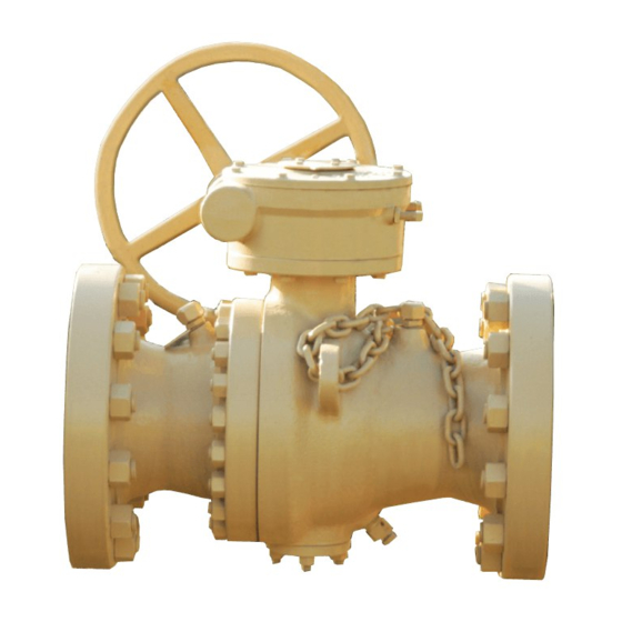
- Page 7 370D6 Standard Wrench Head Valve (see parts list in Table 2) Figure 2 – 370D6 Series Standard Wrench Head Valve TC-003001-30 / Rev 01 Feb-02...
- Page 8 Table 2 – Parts List for Standard Wrench Head Valve Item Description Body Tailpiece Lower Cover Plate Wrench Plate Body Studs Body Nuts Cap Screws – Lower Cover Plate / Wrench Plate Trunnion Bearing Lower Stem Bearing Upper Stem Bearing Stem Key Nameplate (Not Shown) Caution Tag (Not Shown)
-
Page 9: Scope
SCOPE 370D6 ball valves 2” FP to 16” FP are full bore, through conduit, bi-directional, anti-blowout stem, double block and bleed in closed and open position, with trunnion mounted ball for easy operation. These valves can be equipped with plastic seat inserts made of RTFE, NYLON, or PEEK as the customer requires. All the seats are self- relieve type seats to eliminate cavity pressure lock. -
Page 10: Nameplate Information
NAMEPLATE INFORMATION The valve information, including trim, is clearly identified on the valve nameplate that is permanently affixed on the valve. Figure 3 shows a standard valve nameplate and Table 4 details the information stamped on the nameplate. Figure 3 – 370D6 Ball Valve Standard Nameplate Table 4 –... -
Page 11: Storage
STORAGE VALVES DELIVERED BY WKM Following testing and prior to shipment, valves are drained of water and through bores and flange faces are coated with grease and covered by protectors. This will protect the valves for a minimum of six months in covered storage from the date of shipment. -
Page 12: Installation
After welding, clean and check the weld bead and repair as required. WKM 370D6 valves are bidirectional and may be installed with either end facing upstream. The valve should be installed in such a way as to facilitate maintenance, easy access to the valve fittings, and actuating operations. -
Page 13: Field Testing
FIELD TESTING When field testing is required, the following procedures are recommended: 1. Ensure that the test fluids are compatible with the valve seat and seal material 2. Flush the system to remove foreign material that may be in the line as a result from installation procedures to avoid damaging the ball and seats 3. -
Page 14: Maintenance Procedures
These valves can be operated by one person. It is recommended that no extensions be used for operating the valve. Using an extension or power tool to operate the valve voids all warranty and claims, and may result in failure. MAINTENANCE PROCEDURES Under normal working conditions, 370D6 ball valves are designed for lengthy, reliable service. -
Page 15: Lubrication - Grease Injection
CAUTION: Open the drain fitting slowly until the pressure in the body cavity has been discharged. Make sure the fitting body does not unscrew while loosening the fitting stem. If necessary, use another wrench to prevent the fitting body from unscrewing. LUBRICATION –... - Page 16 Flush Valve flush Headquarters Standard valve lubricant WKM 58G 2000 light lube Natural Cameron Valves & Measurement Standard sealant WKM 103 80 bulk/ 80-HS stick 3250 Brairpark Drive, Suite 300 Standard low Temp. 50 bulk / stick Houston, TX 77042...
- Page 17 Standard low Temp. 65 bulk / stick www.c-a-m.com Severe leak sealant 80+PTFE bulk / stick Flush Valve flush Standard valve lubricant WKM 58G 2300 light lube Standard sealant WKM 103 302 bulk / stick Dry CO2 VAL-TEX Standard low Temp. 65 bulk / stick Valves Inc.
-
Page 18: 370D6 Valve Reconditioning
Figure 8 – Air Over Hydraulic Foot Pump Figure 9 – Adapter Fitting Part No. 2330398-01 Part No. K296434 370D6 VALVE RECONDITIONING The 370D6 valves can be rebuilt if necessary. The disassembly and reassembly of the valve requires proper lifting equipment and normal maintenance tools. -
Page 19: Cleaning
6. Remove stem key. Unscrew the adapter plate or lever plate cap screws and remove the adapter plate paying attention not to damage the torque pins. 7. Unscrew the stem grease fitting and the plug (if applicable), unscrew the stem retainer screw(s) and remove it. -
Page 20: Inspection
Clean the sealing rings and the gaskets with a soft cloth. If necessary, wash them with soap and rinse them with clean water. INSPECTION After cleaning, all valve components should be inspected for damage, dents, scoring, wear, or corrosion. If any damage is found, proceed with the repair where possible or with replacement of the parts. - Page 21 3. Inspect the seats, paying careful attention to the insert sealing surfaces. Reject and replace all seats with dings, scratches, or any other physical defects. Install the O-rings and the backup ring. The back-up ring should be on the head side of the seat as shown in Fig. 10. Apply lubricant until completely covering the O-rings and back-up ring.
- Page 22 6. Install the ball thrust washer (if applicable) and the trunnion radial bearing in the ball trunnion bore. 7. Grease the ball drive pin holes and install the drive pins. Make sure the drive pins are placed correctly in the holes and do not stick above the ball. 8.
- Page 23 Figure 13 – Stem Orientation for Installation 17. If a wrench operated valve, use the following procedure to install the wrench (as detailed in Fig. 14): Install the stem thrust washer over the stem with the Teflon backing oriented towards the ball. b.
- Page 24 Install the torque pins and the locating pin into the correctly sized holes. Install the gear adapter plate over the stem. The plate should fit over all the pins including the locating pin, with the key grooves oriented towards the valve body markings and the tailpiece. Install all the cap screws and torque as required per Table 7.
-
Page 25: Gear Operator Assembly
GEAR OPERATOR ASSEMBLY Contact a WKM Representative for part numbers and other relevant information to select the proper gear operator. The gear can be installed in two positions, with the gear shaft on either side of the valve so the valve can be operated from either side of the pipeline. - Page 26 Figure 16 – Gear Operator Assembly 8. After setting the closed stop a quick check can verify that is has been correctly set. Turn the hand wheel gear shaft towards the open position, and then return the valve to the closed position until contacting the closed stop.
-
Page 27: Assembly Torque Values
9. To set the open stop, turn the hand wheel gear shaft counter clockwise until the key stops on the adapter plate groove. Look into the bore of the valve, the flow bore of the ball should be aligned with the flow bore of the seat assembles with not more than 1/16”... -
Page 28: Troubleshooting
TROUBLESHOOTING Table 9 –Troubleshooting Issue Probable Cause Repair Inject antifreeze solution into valve body. Iced up due to restricted flow or low Check the compatibility of antifreeze solution temperature to avoid damaging the seals. Drain periodically Will not open or close to eliminate water accumulation Improper setting of gear or actuator Reset gear or actuator stops... -
Page 29: Contact Information
CONTACT INFORMATION HEADQUARTERS 3250 Briarpark Drive, Suite 300 Houston, TX 77042 Tel 281 499 8511 MANUFACTURING 845 SE 29 Street Oklahoma City, OK 73129 Tel 405 631 1321 For more information: www.c-a-m.com/DEMCO DEMCO@c-a-m.com TC-003001-30 / Rev 01 Feb-02...
Need help?
Do you have a question about the WKM 370D6 and is the answer not in the manual?
Questions and answers