
Related Manuals for Cameron WKM MB


Summary of Contents for Cameron WKM MB
- Page 1 Document Number: TC003001-10 Revision: Rev 2 WKM® Model MB DynaCentric® High Performance Butterfly Valve Installation, Operation, and Maintenance Manual...
-
Page 2: Table Of Contents
TROUBLESHOOTING ..............................13 CONTACT INFORMATION ............................14 All the information contained in this manual is the exclusive property of Cameron. Any reproduction or use of the calculations, drawings, photographs, procedures or instructions, either expressed or implied, is forbidden without the written permission of Cameron or its authorized agent. -
Page 3: Bill Of Materials
BILL OF MATERIALS Figure 1 - Cameron Valves' WKM 2 1/2" - 24" Class 150 and 300 DynaCentric Wafer Valve Components Table 1 - Cameron Valves' WKM 2 1/2" - 24" Class 150 and 300 DynaCentric Wafer Valve Components Item Description... - Page 4 Figure 2 - Cameron Valves' WKM 2 1/2" - 36" Class 150 and 300 DynaCentric Lug Valve Components Table 2 - Cameron Valves' WKM 2 1/2" - 36" Class 150 and 300 DynaCentric Lug Valve Components Item Description Item Description...
-
Page 5: Catalog Number Information
Figure 3 - Detail of Lower Stem & Bottom Cap (10" 300 and larger and 12” 150 and larger) CATALOG NUMBER INFORMATION Table 3 B5XXX Size Body Trim Seal Packing Actuation Inches Group Group Group Group 1 1/2" TFE VEE Bare Stem Class Material... -
Page 6: Scope
SCOPE The WKM DynaCentric MB High Performance Butterfly Valve offers all the benefits of a wafer valve: smaller size, lower price, lighter weight and throttling capabilities as well as the high performance characteristics of ball and gate valves. Because of their quarter turn operation, they are easily and economically adapted to power actuation. The WKM DynaCentric MB High Performance Butterfly Valve is available in 2-1/2"... -
Page 7: Installation And Operation Instructions
Flange protection is provided for all valves. Valves should be stored in a clean, dry location. Outdoor storage is permissible, but should be off the ground and protected from the elements. For long term storage, contact your Cameron representative. INSTALLATION AND OPERATION INSTRUCTIONS... -
Page 8: Initial Installation
Note: some installations may present unique circumstances that may require installation in a position different than outlined above. INITIAL INSTALLATION Raised Face Area The following procedure applies to new installation between standard ASME B16.5 and B16.47 series A pipe flanges. When replacing a valve from an existing installation, clean the flange faces of any residual gasket material before starting. -
Page 9: End-Of-Line Service
END-OF-LINE SERVICE Threaded style lug valves are recommended for end-of-line or equipment isolation service. To prevent unintentional removal of the seat retainer while under pressure, the valve must be installed with the seat retainer against the upstream flange (Figure 12). Seat Retainer Figure 12 GASKETS... -
Page 10: Disk And Pipe Clearance
Table 6 Wafer Body Lug Body Valve Bolt Bolt Size Circle Capscrew Stud Capscrew Size Qty. Qty. Length 'B' (in.) Dia. (in.) Length 'A' Length 'B' 2 1/2" - 150 5 1/2 5/8-11 UNC 5.25 1.75 Wafer Body 2 1/2" - 300 5 7/8 3/4-10 UNC 5.75... - Page 11 ØD Minimum Disc/Pipe 30° Clearance X Figure 15 Table 7 Valve Size and Schedule Schedule Minimum Class Pipe I.D. 2 1/2" - 150 1.69 2 1/2" - 300 1.69 3" - 150 2.63 3" - 300 2.63 4" - 150 3.65 4"...
-
Page 12: Operation
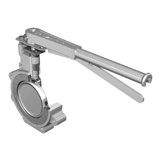
OPERATION MANUALLY OPERATED The WKM DynaCentric MB High Performance Butterfly Valve operates from fully open to fully closed by a 90° turn of the handle. Visual "OPEN - CLOSED" indicators on the stop plate and handle enable the valve's position to be determined at a glance. The 3"... -
Page 13: Maintenance Procedures
Handle or actuator does not provide proper Restrain handle or actuator when in closes with line flow restraint. static position. * Contact your Cameron representative for technical information or repair manual. Additional information is also available on-line at www.c-a-m.com TC-003001-10/ Rev 2... -
Page 14: Contact Information
CONTACT INFORMATION HEADQUARTERS 3250 Briarpark Drive, Suite 300 Houston, TX 77042 Tel 281 499 8511 MANUFACTURING 845 SE 29 Street Oklahoma City, OK 73143 Tel 405 631 1321 For more information: www.c-a-m.com/WKM WKM@c-a-m.com TC-003001-10/ Rev 2...
Need help?
Do you have a question about the WKM MB and is the answer not in the manual?
Questions and answers