Advertisement
Quick Links
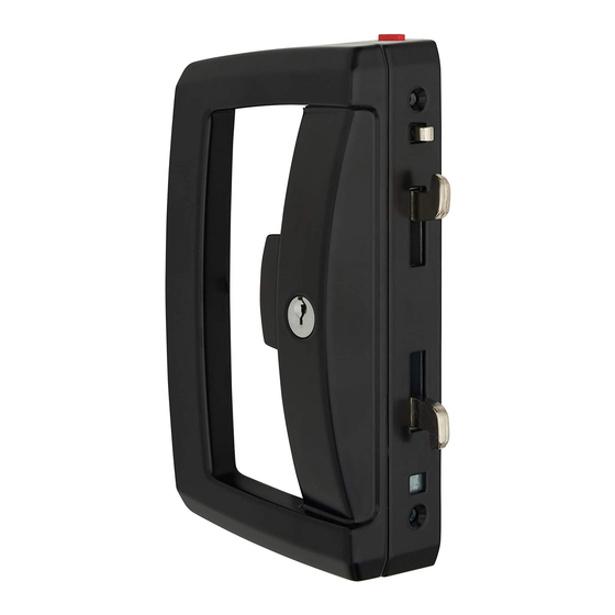
Sliding Door Lock
Installation Instructions
Pack Contents
28mm Screws
Cylinder
Wedge
D-Handle
1. Door Preparation
Note: If the Flat Outer Pull option is being fitted, drill centre hole ø4mm and refer to step 9.
Outer Edge
Back Wall
X
Surface Fix (Follow holes labelled A)
• Ensure door is closed correctly. Place
template on the inside surface of the jamb
(fixed door frame) at the desired height
• If 'X' is greater than 19mm, align 'LINE 1'
with the outer edge
• If 'X' is less than 19mm align 'LINE 2'
against the back wall
• Mark and drill all holes marked 'A'
ø
ø
(3x
10mm, 2x
3mm)
ø
• For 3x
10mm holes - do not fold
template over outer edge step
Template
11
FIXED DOOR FRAME FRONT EDGE
Application: Provides safe latching or secure deadlocking for sliding
aluminium and timber doors.
Operation:
Snib to latch, key to deadlock.
Cylinder
Chassis
Fixing Screws
Lock Chassis
Side Fix (Follow holes labelled B)
• Fold template 90° along 'LINE 1'
• Ensure door is closed correctly. Place
template against the door surface at
the desired height
• Mark and drill all holes marked 'B'
ø
ø
(3x
10mm, 2x
3mm)
75
62.5
BACK WALL OF JAMB
ø
10
41
Cylinder with Tail
Cylinder Retainer
2. Lock Chassis and Handle Preparation
Press in
DCD Button
Locked
Position
Snib Button
3. Cylinder Preparation
• Place the cylinder with tail in the outer
• Place the outer pull on the external face of
pull and place cylinder retainer over
the back of the cylinder as shown
75
62.5
ø
3
33
16
41
Tools Required:
• Drill
• Phillips Screwdriver •
ø
•
3mm Drill Bit
• Hacksaw or cutters • Rule and pencil or marker
7mm Screws
Outer Pull
• Remove components from packaging.
• Press in the DCD (door closed detect)
• Mark and cut the cylinder tail piece 10-
the door with the tail passing through the
centre hole
4. Screw Selection
• Several chassis fixing screws are
LINE 2
• Screws are a "taptite" screw that makes
LINE 1
• Use the table to identify
Door Thickness
19-29mm
30-39mm
40-49mm
ø
10mm Drill Bit
16mm Fixing
Screws
Strike Body
Strike Cover
If beaks are in the locked position shown,
push the snib button down to retract
the beaks
button and remove the lock chassis from
inside the D-Handle body
10-12mm
12mm past the door (allow an extra 5mm
if a handle packer is to be fitted)
provided to suit different door
thicknesses
its own thread – therefore the outer
pulls are not pre threaded
which are the correct
length fixing screws for
your application
Screw Selection
M4 x 50mm
M4 x 60mm
M4 x 70mm
Advertisement

Related Manuals for Assa Abloy Lockwood Onyx 9A1A2/5PBLK


Summary of Contents for Assa Abloy Lockwood Onyx 9A1A2/5PBLK
- Page 1 Sliding Door Lock Installation Instructions Application: Provides safe latching or secure deadlocking for sliding Tools Required: ø aluminium and timber doors. • Drill • Phillips Screwdriver • 10mm Drill Bit ø Operation: Snib to latch, key to deadlock. • 3mm Drill Bit •...
- Page 2 • Place cylinder with tail bar into 6-pin cylinder retainer • Fit outer pull to door as shown in Step 5 ASSA ABLOY New Zealand Limited ASSA ABLOY Australia Pty Limited 6 Armstrong Road, Albany, Auckland 0632 235 Huntingdale Road, Oakleigh, Vic 3166 info.nz@assaabloy.com...
Need help?
Do you have a question about the Lockwood Onyx 9A1A2/5PBLK and is the answer not in the manual?
Questions and answers
Trying to install new Lockwood Onyx sliding door lock. Lock still in parts. Squb is jammed open and cannot move slide up or down Red tab is in down position. See photo of lock internals.