Advertisement
Quick Links
B.E.G.
MINI-S-PP-FC
Controls
Installation and Operating Instruction for B.E.G. Controls - Secondary sensor MINI-S-PP-FC
1. Product information
•
MINI secondary sensor, requires connection to
primary MINI-P-PP-A-FC sensor and PP-A-J or PP-1-J
power pack or proprietary low voltage system
•
Designed for indoor locations
•
Up to 4 secondary sensors may be connected with
a primary sensor to increase detection coverage.
•
Spring clips for quick and easy installation in
suspended ceilings and light fixtures
•
5-year limited warranty
•
Masking blinds included
•
ROHS compliant
2. Operation with power pack
PP-A-J and PP-1-J
The MINI-P with B.E.G. PP-A power pack detects both
motion and the ambient light level in the room and
then automates the lights according to the parameters
set by the installer or the building management. The
MINI-S extends the motion detection coverage of
the system. The integrated light sensor in the MINI-P
constantly measures the ambient light and if the light
level is sufficient, the light will be switched off. If the
ambient light level is below the preset brightness level
the lights will be allowed to come on when the sensors
detect movement in the room.
When motion is detected in the room the PP-A's
auxiliary dry contact relay will send a signal to
HVAC or other systems indicating that the room
is occupied. With the integration of simple off the
shelf, normally-open momentary switches, the MINI-
PP-A can be set to operate in vacancy mode via the
auto/manual switch selector on the power pack.
3. Safety information
Work should be carried out by qualified pro-
fessionals or by instructed persons under the
!
direction and supervision of qualified skilled
electrical personnel in accordance with electri-
cal regulations.
The device is not to be used to isolate other
!
equipment from the mains supply!
4. Mounting
Select sensor(s) mounting location based on room di-
mensions and sensor coverage pattern. Avoid placing
sensor(s) less than four feet away from a heat and/
or ventilation sources. Avoid placing sensor(s) where
view will be directed
≤1.3 in
outside of intended
≤ 34 mm
controlled space, this
to prevent outside
sources from activating
sensor(s).
A circular opening
1.3 in/34 mm in diam-
eter must be made in
the ceiling.
Having connected
the cables in accordance with the national and local
electrical codes, connect the sensor to the power pack
using the RJ12 connector. Pass sensor's RJ12 connec-
tor through ceiling opening. Next, squeeze spring
clips through ceiling opening. Sensor should clip
securely into place.
(See Figure)
When using primary and secondary devices,
please mount the primary device at the place
with the least amount of natural light.
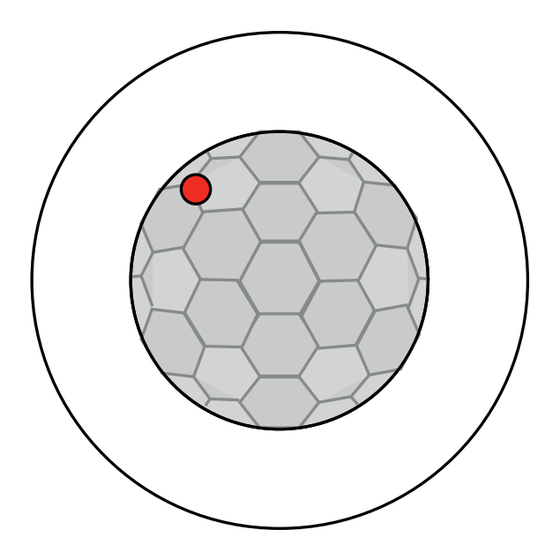
5. Position LED
LED 1 red
1
6. Self test cycle/Startup behavior
When power is first applied, the sensor enters an
initial 60 second self-test cycle. During this time the
device does not respond to movement and stays on.
7. Range
RJ 12
1
8 ft/2.50 m
2
3
3
1
8. Exclude sources of interference
To prevent false activation from external heat-emitting
sources, use blinds to mask sensor viewing angle.
9. Decription / Part No. / Accessory
Description
MINI-S-PP-FC
MINI-P-PP-A-FC
Remote control:
via B.E.G. Controls IR-Adapter
Power pack PP-A-J
Power pack PP-1-J
The required app for smartphones can be down-
loaded from the App Store for iOS smartphones and
Google Play Store for Android smartphones.
Remote only works with primary MINI-P-PP-A-FC
!
sensor!
10. Technical data
Power supply:
Pulse output:
Pulse duration:
Ambient temperature: -13°F-122°F/-25°C to +50°C
Protection/Polution degree:
Recommended height
for mounting:
Range of coverage Ø H 8.2 ft/2.50 m :
Area of coverage:
Dimensions:
Walking across
quer zum Melder gehen
quer zum Melder gehen
quer zum Melder gehen
Type 1 Actions
frontal zum Melder gehen
Walking towards
frontal zum Melder gehen
frontal zum Melder gehen
Unterkriechschutz
Unterkriechschutz
Seated
Unterkriechschutz
11. Manual switching
See manual of the power pack PP-A/PP-1: "PB
!
load" and "All off" (only PP-A)!
2
12. LED-functional indicators
LED activity after sensor is energized (60 second
self-test cycle period).
Operating state LED function indicators
Self-test cycle
LED function indicators during operation
Process
Motion detection
13. MINI-S-PP-FC - Connection
Connect the B.E.G. Controls MINI-S-PP-FC and the
MINI-P-PP-A-FC sensor to the PP-A-J or PP-1-J power
Part No.
pack using the sensor's RJ12 connector and splitter.
97183
NOTE:
97180
Splitter: (RJ12 male to dual RJ12 female included
92726
with every secondary mini sensor)
97020
97036
USA-EN
24 V DC
Digital output
1sec. ON, 9 sec. OFF
IP20 / II
8 - 10 ft / 2.44 - 3.05 m
seated 13 ft /4 m
walking across 33 ft /10 m
walking towards 19.7 ft /6 m
360°
H 1.1in x Ø 1.42 in
H 28 x Ø 36 mm
Red blinks once per second and
for 60 seconds
LED function indicators
Red LED flashes on each
detected movement
Splitter
RJ12
Advertisement

Related Manuals for B.E.G. MINI-S-PP-FC


Summary of Contents for B.E.G. MINI-S-PP-FC
- Page 1 USA-EN B.E.G. MINI-S-PP-FC Controls Installation and Operating Instruction for B.E.G. Controls - Secondary sensor MINI-S-PP-FC 1. Product information 5. Position LED 10. Technical data • MINI secondary sensor, requires connection to Power supply: 24 V DC LED 1 red primary MINI-P-PP-A-FC sensor and PP-A-J or PP-1-J...
- Page 2 14. Wiring diagrams with Power pack PP-A-J and PP-1-J Standard mode with Primary/Secondary Load LED Switch Load Black LED Switch Black Power Pack Power Pack 120 - 277 VAC 120 - 277 VAC Switch Switch PP-A-J PP-1-J Neutral White Neutral White Y / R HVAC...
Need help?
Do you have a question about the MINI-S-PP-FC and is the answer not in the manual?
Questions and answers