Sentiotec Pro B2 Instructions For Installation And Use Manual
Sauna control unit
Hide thumbs
Also See for Pro B2:
- Instructions for installation and use manual (152 pages) ,
- Instructions for installation and use manual (62 pages) ,
- Instructions for installation and use manual (268 pages)

Related Manuals for Sentiotec Pro B2


Summary of Contents for Sentiotec Pro B2
- Page 1 Sauna control unit Pro B2 PRO-B2 INSTRUCTIONS FOR INSTALLATION AND USE English Version 12/13 ID no. 50950096...
-
Page 2: Table Of Contents
Table of Contents 1. About this instruction manual 2. Important information for your safety 2.1. Intended use 2.2. Safety information for the installer 2.3. Safety information for the user 3. Product description 3.1. Scope of delivery 3.2. Optional accessories 3.3. Product functions 3.4. - Page 3 8. Starting-up 8.1. Setting the heating period limit 8.2. Activating/deactivating phase alignment 8.3. Activating/deactivating the remote start and preset time function 8.4. Activating/deactivating the single-sensor mode 8.5. Displaying the heater temperature in single-sensor mode 9. Operation 9.1. Operating elements 9.2. Switching on the light 9.3.
-
Page 4: About This Instruction Manual
These instructions for installation and use can also be found in the down- loads section of our website: www.sentiotec.com. Symbols used for warning notices In these instructions for installation and use, a warning notice located next to an activity indicates that this activity poses a risk. -
Page 5: Important Information For Your Safety
The sauna control unit Pro B2 is used exclusively for operating and controlling the sauna functions in accordance with the technical data. The sauna control unit Pro B2 may only be used for operating and controlling a sauna heater which has been certii ed as satisfying the combustion test described in paragraph 19.101 of EN 60335-2-53. -
Page 6: Safety Information For The User
Instructions for installation and use p. 6/30 ● A three-phase shut-off device with a 3 mm contact opening must be provided during installation. This is provided by the fuse. ● The sauna control unit must be installed outside the sauna room at a height of approx. - Page 7 Instructions for installation and use p. 7/30 ● For health reasons, do not use the sauna when under the inl u- ence of alcohol, medication or drugs. ● Make sure that no l ammable objects have been placed on the sauna heater before the sauna control unit is switched on.
-
Page 8: Product Description
● Safety shut-off (item number: HT-SWL) 3.3. Product functions The sauna control unit Pro B2 features the following functions: ● Regulation of sauna heaters with a heating output of up to 10.5 kW in the temperature range spanning 30 °C to 110 °C. -
Page 9: Sensor Operating Modes
Instructions for installation and use p. 9/30 3.4. Sensor operating modes The sauna control unit can be operated with one or two temperature sensors. Single-sensor mode (F1) Single-sensor mode must be activated when starting up the sauna for the i rst time (see 8.4. -
Page 10: Installation
Installation instructions, only for experts p. 10/30 Installation 4.1. Installing the sauna control unit ATTENTION! Damage to the unit The sauna control unit is protected against jets of water, however direct contact with water could still damage the unit. ● Install the sauna control unit in a dry place at which a maximum humidity of 95% is not exceeded. - Page 11 Installation instructions, only for experts p. 11/30 To install the sauna control unit, perform the following steps: 1. Screw two Phillips-head screws (16 mm) into the wall of the sauna at a height of approx. 1.70 m to a distance of up to 7 mm. The two screws must be placed at a distance of 145 mm from each other (see Fig.
-
Page 12: Installing The Heater Sensor F1 With Excess Temperature Fuse
Installation instructions, only for experts p. 12/30 4.2. Installing the heater sensor F1 with excess temperature fuse Observe the following points when installing the heater sensor: ● The heater sensor must be installed on the rear of the heater, above the mid- dle of the sauna heater. -
Page 13: Installing Bench Sensor F2 (Optional)
Installation instructions, only for experts p. 13/30 4.3. Installing bench sensor F2 (optional) The bench sensor must be installed on the wall of the sauna room, above the rear bench seat. An interval of approx. 15 cm to the roof of the sauna room must be maintained. -
Page 14: Electrical Connection
Installation instructions, only for experts p. 14/30 Electrical connection ATTENTION! Damage to the unit ● The sauna control unit may only be used for operating and controlling 3 heat- ing circuits with a maximum heating capacity of 3.5 kW per heating circuit. Low-voltage connection area Cable bushing for heater wire Terminal strips for safety shut-off device,... -
Page 15: Connecting The Power Supply Cable And Heater Cable
Installation instructions, only for experts p. 15/30 Observe the following points when connecting the power to the sauna control unit: ● Installation may only be performed by a qualii ed electrician or similarly quali- i ed person. Please observe that in the event of a guarantee claim, a copy of the bill from the electrician performing the work must be presented. -
Page 16: Connecting The Power Booster (Optional)
Installation instructions, only for experts p. 16/30 5.3. Connecting the power booster (optional) 1. Guide the cable for the power booster through the cable bushing into the connection area for 230 V/400 V 2. Connect the cable for the power booster to the terminal strip accordance with the connection diagram. -
Page 17: Remote Start
Installation instructions, only for experts p. 17/30 To install the safety shut-off device, perform the following steps: 1. Install the safety shut-off device in accordance with the operating instruc- tions for the device. 2. Guide the wires for the safety shut-off device through the cable bushing into the low-voltage connection area 3. -
Page 18: Performing Tests
Installation instructions, only for experts p. 18/30 Performing tests The following tests must be performed by a certiied electrical itter. WARNING! The following tests must be performed with the power supply switched on. There is a danger of electric shock. ●... - Page 19 Installation instructions, only for experts p. 19/30 5. When there is an optional power booster: a. Check the control wires ST1, ST2 and ST3. b. Check the maximum permissible heating output of 3 kW per phase on the power booster S2-18. c.
-
Page 20: Connection Diagram
Fig. 4 Connection diagram 1 Remote start 2 Heating system (max. 10.5 kW) 139 °C 3 Sauna control unit power supply 4 Power booster 5 Light 6 Earth rail 7 Heater sensor with excess temperature fuse (F1) 8 Bench sensor (F2) -
Page 21: Starting-Up
Installation instructions, only for experts p. 21/30 Starting-up The function selection switch in the low-voltage connection area allows a variety of product functions to be activated. The figure at the right shows the standard setting for the function selection switch. Fig. -
Page 22: Activating/Deactivating Phase Alignment
Installation instructions, only for experts p. 22/30 8.2. Activating/deactivating phase alignment Phase alignment is activated or deactivated using the function selection switch 3. ● The function selection switch 3 is set to the ON position as standard. Phase alignment is therefore activated. ●... -
Page 23: Activating/Deactivating The Single-Sensor Mode
Installation instructions, only for experts p. 23/30 8.4. Activating/deactivating the single-sensor mode In single-sensor mode, the sauna control unit is operated with the heater sensor with an excess temperature fuse (F1) only. The single-sensor mode must be activated above the function selection switch 5. ●... -
Page 24: Operation
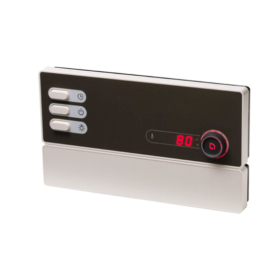
Instructions for use for the user p. 24/30 Operation 9.1. Operating elements Additional display Light switch Temperature selector ON/OFF switch Temperature display Preset time button 9.2. Switching on the light The light in the sauna room can be switched on and off independently of the ON/OFF switch ●... -
Page 25: Switching On The Sauna Control Unit
Instructions for use for the user p. 25/30 9.3. Switching on the sauna control unit WARNING! Risk of i re Flammable objects that are placed on the sauna heater could ignite and cause i res. ● NEVER place l ammable objects on the sauna heater. ●... -
Page 26: Changing The Preset Temperature
Instructions for use for the user p. 26/30 9.5. Changing the preset temperature You can change the preset temperature during operation any time. ● Turn the temperature selector to the right to increase the temperature. Turn the temperature selector to the left to decrease the temperature. ►... -
Page 27: Cancelling The Preset Time Function
Instructions for use for the user p. 27/30 9.7. Cancelling the preset time function ● Press and hold down the preset time button for a second to cancel the preset time function. ► The preset time countdown is cancelled. ► Then the current temperature in the sauna room is displayed in the temperature display . -
Page 28: Cleaning And Maintenance
Instructions for use for the user p. 28/30 10. Cleaning and maintenance 10.1. Cleaning ATTENTION! Damage to the unit The sauna control unit is protected against jets of water, however direct contact with water could still damage the unit. ● Never immerse the device in water. ●... -
Page 29: Troubleshooting
Instructions for use for the user p. 29/30 12. Troubleshooting Error messages The sauna control unit is equipped with diagnostic software which monitors system statuses when it switches on and during operation. As soon as the diagnostic software identii es an error, the sauna control unit switches the sauna heater off. Errors are indicated by a recurring warning tone and by l ashing on the tempera- ture selector . -
Page 30: Technical Data
Instructions for use for the user p. 30/30 13. Technical data Ambient conditions Storage temperature: -25 °C to +70 °C Ambient temperature: -10 °C to +40 °C Relative humidity: max. 95% Sauna control unit Dimensions: 307 x 175 x 57 mm Switched voltage/three-phase 3N: 400 V AC Frequency:... - Page 31 à votre sécurité. Vous trouverez également ces instructions de montage et ce mode d’emploi dans la rubrique de téléchargement de notre site Internet www.sentiotec.com. Symboles d’avertissement Dans les instructions de montage et le mode d’emploi présents, un avertissement précède les activités représentant un danger. Conformez-vous impérativement à...
- Page 32 NOTIZEN / APPUNTI / NOTES / NOTE / NOTITIES ………………………………………………….....………………………………………………………………... ……………………………………………………………..……………………………………………………………... …………………………………………………………….....………………………………………………………... …………………………………………………….....………………………………………………………………... ……………………………………………………………..……………………………………………………………... ……………………………………………………………..……………………………………………………………... ……………………………………………………………..…………………………………………………………... …………………………………………………………….....………………………………………………………... …………………………………………………………….....………………………………………………………... …………………………………………………………….....………………………………………………………... …………………………………………………………….....………………………………………………………... …………………………………………………………….....………………………………………………………..…………………………………………………………….....………………………………………………………... …………………………………………………………….....………………………………………………………... …………………………………………………………….....………………………………………………………... …………………………………………………………….....………………………………………………………... …………………………………………………………….....………………………………………………………... …………………………………………………………….....………………………………………………………... …………………………………………………………….....………………………………………………………... WORLD OF WELLNESS...
- Page 33 GmbH world of wellness Oberregauer Straße 48 4844 Regau, Austria T +43 (0) 7672/277 20-800 F +43 (0) 7672/277 20-801 E info@sentiotec.com www.sentiotec.com...
Need help?
Do you have a question about the Pro B2 and is the answer not in the manual?
Questions and answers