System Sensor B402B Installation And Maintenance Instructions
Plug-in detector base, for use with the following smoke detectors: 1451, 2451, and 2451th
Hide thumbs
Also See for B402B:
Table of Contents
Advertisement
Quick Links
INSTALLATION AND MAINTENANCE INSTRUCTIONS
B402B Plug-in Detector Base
For use with the following smoke detectors:
1451, 2451, and 2451TH
Specifications
Base Diameter:
Base Height:
Weight:
Operating Temperature Range:
Operating Humidity Range:
Electrical Ratings — includes base and detector
System Voltage:
Maximum Ripple Voltage:
Start-up Capacitance:
Standby Ratings:
Alarm Ratings:
Reset Voltage:
Reset Time:
Start-up Time:
Relay Contact Ratings
Resistive or Inductive (60% Power Factor):
Form A:
Form C:
Before Installing
Please read the System Sensor manual I56-407, Guide for
Proper Use of System Smoke Detectors, which provides
detailed information on detector spacing, placement, zon-
ing, wiring, and special applications. Copies of this manual
are available at no charge from System Sensor. (For instal-
lations in Canada, refer to CAN4-S524, Standard for the
Installation of Fire Alarm Systems, and CEC Part 1, Sec. 32.)
NOTICE: This manual should be left with the owner/user
of this equipment.
IMPORTANT: The detector used with this base must be
tested and maintained regularly following NFPA 72 require-
ments. The detector used with this base should be cleaned
at least once a year.
D450-03-00
6.2 inches (15.7 cm)
1.1 inches (2.8 cm)
0.3 lb. (130 g)
4 inch square box with or without plaster ring. Min. Depth: 1.5 inches
4 inch octagon box. Min. Depth: 1.5 inches
3-1/2 inch octagon box. Min. Depth: 1.5 inches
0° to +49°C (32° to 120°F)
10% to 93 % Relative Humidity, Non-condensing
24 VDC
4 Volts peak to peak
0.02 µF Maximum
20 VDC Minimum
29 VDC Maximum
120 µA Maximum
17 mA Minimum
36 mA Maximum
1.4 VDC Minimum
0.3 Seconds Maximum
(If used, the RA400 remote lamp operates within the specified
detector alarm currents.)
34.0 Seconds Maximum
2.0A @ 30 VAC/DC
2.0A @ 30 VAC/DC
0.6A @ 110 VDC
1.0A @ 125 VAC
1
3825 Ohio Avenue, St. Charles, Illinois 60174
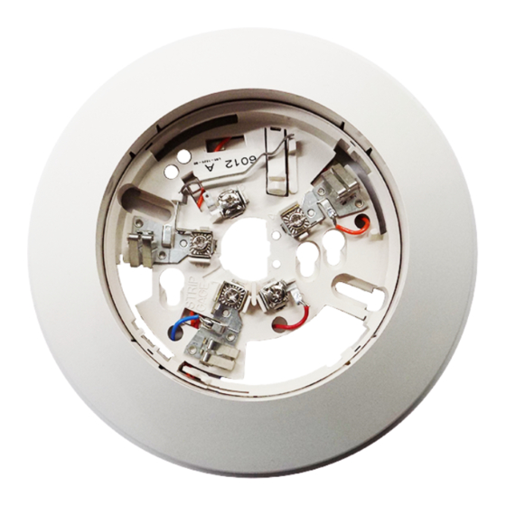
General Description
The plug-in detector base B402B is used with System
Sensor model 2451 and 2451TH photoelectronic detector
heads, and model 1451 ionization detector head. The capa-
bility of plugging these detectors into a variety of special
bases makes them more versatile than equivalent direct-
wired models. Refer to the System Sensor catalog for other
available plug-in detector bases.
This B402B base is intended for use in 4-wire systems, with
screw terminals provided for power, remote annunciator,
and relay contact connections. These bases also contain a
resistor to provide current limiting in the alarm state.
1-800-SENSOR2, FAX: 630-377-6495
I56-374-05R
Advertisement
Table of Contents

Related Manuals for System Sensor B402B


Summary of Contents for System Sensor B402B
- Page 1 Installation of Fire Alarm Systems, and CEC Part 1, Sec. 32.) available plug-in detector bases. NOTICE: This manual should be left with the owner/user This B402B base is intended for use in 4-wire systems, with of this equipment. screw terminals provided for power, remote annunciator, and relay contact connections.
- Page 2 Mounting Figure 1. Mounting base to box: This detector base mounts directly to 3 ⁄ -inch and 4-inch octagon boxes, and 4-inch square boxes (with or without plaster). To mount the base, remove the decorative ring by rotating it in either direction to unhook the snaps before separating the ring from the base.
- Page 3 NOTE: For wiring or releasing device, refer to manufac- turer's installation instructions. CAUTION For system supervision–DO NOT use looped wire under ter- minals 2, 3, and 5. Break wire run to provide supervision of system. Figure 2. Typical wiring diagram: D450-03-00 I56-374-05R...
- Page 4 Please refer to insert for the Limitations of Fire Alarm Systems Three-Year Limited Warranty System Sensor warrants its enclosed smoke detector base to be free from Sensor, Repair Department, RA #__________, 3825 Ohio Avenue, St. defects in materials and workmanship under normal use and service for a Charles, IL 60174.
Need help?
Do you have a question about the B402B and is the answer not in the manual?
Questions and answers