Advertisement
INSTALLATION AND MAINTENANCE INSTRUCTIONS
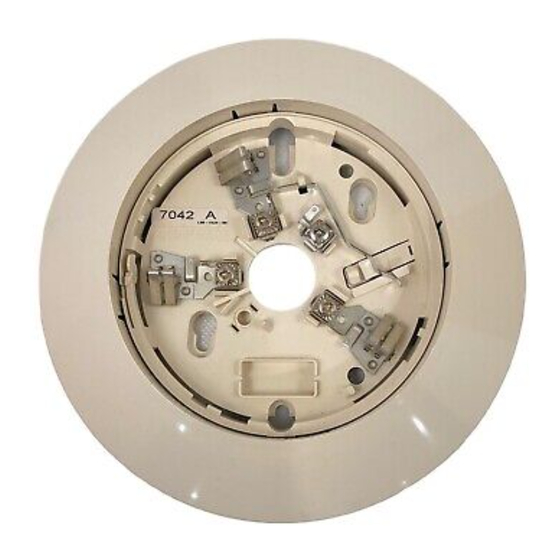
B401B Plug-in Detector Base
For use with the following smoke detectors:
1451, 2451, and 2451TH
Specifications
Base Diameter:
Base Height:
Weight:
Operating Temperature Range:
Operating Humidity Range:
Electrical Ratings — includes base and detector
System Voltage:
Maximum Ripple Voltage:
Start-up Capacitance:
Standby Ratings:
Alarm Ratings:
Reset Voltage:
Reset Time:
Start-up Time:
Before Installing
Please thoroughly read the System Sensor manual I56-407,
Guide for Proper Use of System Smoke Detectors, which pro-
vides detailed information on detector spacing, placement,
zoning, wiring, and special applications. Copies of this man-
ual are available at no charge from System Sensor. (For instal-
lations in Canada, refer to CAN4-S524, Standard for the
Installation of Fire Alarm Systems, and CEC Part 1, Sec. 32.)
NOTICE: This manual should be left with the owner/user
of this equipment.
IMPORTANT: The detector used with this base must be
tested and maintained regularly following NFPA 72 require-
ments. The detector used with this base should be cleaned
at least once a year.
D450-01-01
6.2 inches (15.7 cm)
1.1 inches (2.8 cm)
0.3 lb. (130 g)
4-inch square box with or without plaster ring. Min. Depth–1.5 inches
4-inch octagon box. Min. Depth–1.5 inches
3
1
⁄
inch octagon box. Min. Depth–1.5 inches
2
0° to +49°C (32° to 120°F)
10% to 93% Relative Humidity, noncondensing
12/24 VDC
4 Volts peak to peak
0.02 µF Maximum
8.5 VDC Minimum; 35 VDC Maximum
120 µA Maximum
4.2 VDC Minimum at 10 mA; 6.6 VDC Maximum at 100 mA
(Alarm current must be limited to 100 mA by the control panel. If used, the RA400
remote lamp operates within specified detector alarm currents.)
2.5 VDC Minimum
0.3 Seconds Maximum
34.0 Seconds Maximum
1
General Description
The B401B plug-in detector base is used with System
Sensor model 2451 and 2451TH photoelectronic detector
heads and model 1451A ionization detector heads. The
capability of plugging these detectors into a variety of spe-
cial bases makes them more versatile than equivalent
direct-wired models. Refer to the System Sensor catalog for
other available plug-in detector bases.
This base is intended for use in 2-wire systems, with screw
terminals provided for power, ground, and remote annun-
ciator connections.
3825 Ohio Avenue
St. Charles, Illinois 60174
1-800-SENSOR2, FAX: 630-377-6495
I56-298-09R
Advertisement
Table of Contents

Subscribe to Our Youtube Channel
Related Manuals for System Sensor B401B


Summary of Contents for System Sensor B401B
- Page 1 Copies of this man- capability of plugging these detectors into a variety of spe- ual are available at no charge from System Sensor. (For instal- cial bases makes them more versatile than equivalent lations in Canada, refer to CAN4-S524, Standard for the direct-wired models.
- Page 2 Mounting Figure 1. Mounting base to box: This detector base mounts directly to 3 ⁄ -inch and 4-inch octagon boxes, and 4-inch square boxes (with or without plaster rings). To mount, remove the decorative ring by turning it in either direction to unhook the snaps, then sep- arate the ring from the base.
- Page 3 To make the detector tamper-resistant, use needle-nose pli- ers to break the smaller tab at the scribed line on the tamp- System Sensor smoke detectors and mounting bases are er-resistance tab. Figure 3A shows the location of this tab marked with a compatibility identifier located as the last on the detector mounting bracket.
- Page 4 Please refer to insert for the Limitations of Fire Alarm Systems Three-Year Limited Warranty System Sensor warrants its enclosed smoke detector base to be free from Charles, IL 60174. Please include a note describing the malfunction and defects in materials and workmanship under normal use and service for a suspected cause of failure.
Need help?
Do you have a question about the B401B and is the answer not in the manual?
Questions and answers