Advertisement
Quick Links
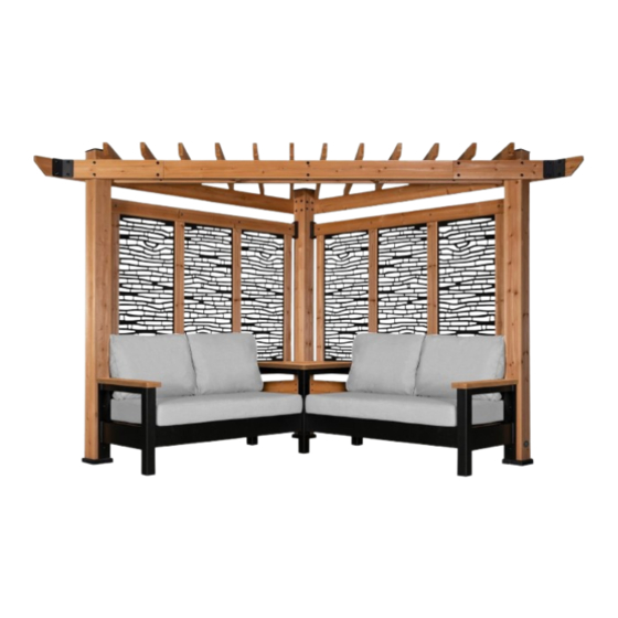
2002517 TUSCANY CABANA
(BAMBOO - CAST PUMICE)
2002555 TUSCANY CABANA
(PEBBLE - CAST PUMICE)
to register your set, or to order replacement parts please visit
SAVE THIS ASSEMBLY MANUAL FOR FUTURE REFERENCE IN THE EVENT THAT
Made in China | INS-2002517-A-TUSCANY CABANA-ENG 0
Model #
2002517, 2002524,
2002531, 2002548,
2002555, 2002562,
2002579, 2002586
2002524 TUSCANY CABANA
(BAMBOO - SPECTRUM INDIGO)
2002562 TUSCANY CABANA
(PEBBLE - SPECTRUM INDIGO)
average 2 person assembly time
assembly time may vary based on skill level
For the most up to date assembly manual,
www.backyarddiscovery.com
YOU NEED TO ORDER REPLACEMENT PARTS.
CABANA
Owner's Manual & Assembly Instructions
2002531 TUSCANY CABANA
(BAMBOO - CAST SLATE)
2002579 TUSCANY CABANA
(PEBBLE - CAST SLATE)
MANUFACTURED BY:
Backyard Discovery
3305 Airport Drive
Pittsburg, KS 66762
800-856-4445
2002548 SIENA CABANA PERGOLA
(BAMBOO PATTERN)
2002586 VERONA CABANA PERGOLA
(PEBBLE PATTERN)
Advertisement

Related Manuals for Backyard Discovery TUSCANY 2002517


Summary of Contents for Backyard Discovery TUSCANY 2002517
- Page 1 Model # 2002517, 2002524, CABANA MANUFACTURED BY: 2002531, 2002548, Backyard Discovery 3305 Airport Drive 2002555, 2002562, Pittsburg, KS 66762 Owner's Manual & Assembly Instructions 2002579, 2002586 800-856-4445 2002517 TUSCANY CABANA 2002524 TUSCANY CABANA 2002531 TUSCANY CABANA 2002548 SIENA CABANA PERGOLA...
- Page 2 INSTALLATION SERVICES AVAILABLE! Need a helping hand? Let our team of professionals handle the installation for you! *Installation services are only available to U.S. customers. With Go Configure, we bring you 18 years of experience right to your doorstep. We service a wide array of indoor and outdoor recreation products that most consumers don’t have the time or ability to deliver &...
- Page 3 Owner’s Manual Please Read This Before Starting Assembly The store where you made your purchase does not stock parts for this item. If you have assembly questions or you are missing or have damaged parts, please call you can also visit www.backyarddiscovery.com or e-mail customerservice@backyarddiscovery.com Please have the following information ready when you make your call: •...
- Page 4 Limited Warranty Please read entire booklet completely before beginning the assembly process For Your Records: Tracking Number Reference Label...
- Page 5 Owner’s Manual Safety Warnings and Maintenance Instructions IT IS IMPORTANT TO CHECK AND TIGHTEN ALL HARDWARE AT THE BEGINNING AND DURING THE SEASON AS THEY MAY LOOSEN DUE TO WOOD EXPANSION AND CONTRACTION. • DO NOT climb or walk on the roof for any reason •...
- Page 6 Owner’s Manual Instructions for Proper Maintenance Your Backyard Discovery structure is designed and constructed of quality materials. As with all outdoor products it will weather and wear. To maximize the enjoyment, safety and life of your structure it is important that you properly maintain it.
- Page 7 Assembly Tips Protrusion Hazard Incorrect Correct If you see exposed threads and your bolt protrudes beyond the T-Nut you may have over tightened the bolt. To eliminate this, remove the bolt and add washers to eliminate the problem. Proper Hardware Assembly Bolt and T-Nut Assembly Tap T-nut into the provided hole.
- Page 8 Owner’s Manual Assembly Tips ASSEMBLY TIP: Keep an eye out for these boxes which will contain helpful pictures and information making the assembly process as quick and painless as possible. Sorting Wood When removing the wood from the boxes we recommend arranging them by part number before you begin assembly.
- Page 9 Owner's Manual Tools Required for Installation 5/16...
- Page 10 Owner's Manual Basic Setup Dimensions & Assembly Notes It is critically important that you start with square and level footings, concrete pad or deck to attach your structure • Pay close attention to the items needed for each step. Make sure you are using the correct hardware for each step. Using incorrect hardware may result in improper assembly •...
- Page 12 9205376 - Parts Identification Owner's Manual Wood Components (Not to Scale) LOWER SUPPORT - W4L13810 1 3/8"x4 3/8"x81 1/4" (36x112x2064) TOP SUPPORT - W4L13809 1 3/8"x4 3/8"x81 1/4" (36x112x2064) LOWER SUPPORT - W4L13835 1 3/8"x4 3/8"x81 1/4" (36x112x2064) JOIST - W4L13812 1 3/8"x5 1/4"x89 1/2"...
- Page 13 9205376 - Parts Identification Owner's Manual Wood Components (Not to Scale) TOP RAIL - W4L13832 1"x5 1/4"x81 1/4" (24x134x2063) BEAM END - W4L13816 1"x5 1/4"x29" (24x134x736) BEAM - W4L13817 1"x5 1/4"x89 1/2" (24x134x2274) BEAM - W4L13818 1"x5 1/4"x71 1/8" (24x134x1807) BEAM - W4L13819 1"x5 1/4"x71 1/8"...
- Page 14 9205376 - Parts Identification Owner's Manual Wood Components (Not to Scale) BEAM END - W4L13830 BEAM END - W4L13831 1"x5 1/4"x29" (24x134x736) 1"x5 1/4"x19" (24x134x484) VERTICAL SUPPORT - W4L13808 1"x3 3/8"x53 7/8" (24x86x1368) W2A02859 5 1/2"x5 1/2"x89 5/8" (140x140x2274) W2A02860 5 1/2"x5 1/2"x89 5/8"...
- Page 15 Owner's Manual 9205376 - Parts Identification Hardware Components H100363 BOLT WH BLK (18) 5/16X6 H100407 H100193 NUT BARREL BOLT WH BLK H100468 BOLT WH BLK (18) WH BLK (18) 5/16x1 1/2 5/16x1 5/16x1-1/2 H100192 NUT BARREL H100825 LAG SCREW (18) WH BLK (38) 5/16x4 BLK...
- Page 16 Owner's Manual 9205376 - Parts Identification Hardware Components H100391 SCREW PFH BLK H100120 SCREW (13) (13) CONCRETE ANCHOR 1/4x2 H100797 SCREW PWH BLK H100392 SCREW PWH BLK H100200 SCREW PFH BLK (76) 8x3/4 (13) 8x1 1/2 H100202 SCREW PWH BLK H100385 SCREW PFH BLK (17)
- Page 17 9205376 - Parts Identification Owner's Manual Accessory Components (Not to Scale) A4M01111 METAL BEAM BYD ID TAG A100241 (SMALL) WITHOUT AGES FOOT 142 A100029 SQUARE POST A4M00555 90° L-BRACKET - MOUNTING A6P00442 BRACKET L BRACKET A4M01108 BRACKET 135° A4M01097 24x30x112 - BLK L BRACKET A4M01166 40x40x112 - BLK...
- Page 18 Owner's Manual 9205109 & 9205116 - Parts Identification Accessory Components (Not to Scale) 9205123 CAST PUMICE A6P00455 BACK CUSHION A6P00454 SEAT CUSHION 9205109 CAST SLATE A6P00393 BACK CUSHION A6P00392 SEAT CUSHION 9205116 SPECTRUM INDIGO A6P00395 BACK CUSHION A6P00394 SEAT CUSHION Owner's Manual 9205352 &...
- Page 19 9205017 - Parts Identification Owner's Manual Accessory Components (Not to Scale) A4M01063 POST A4M01069 POST A4M01070 POST A4M01105 ARM POST - LEFT A4M01060 A4M01066 FRAME END - RIGHT FRAME RAIL - RIGHT A4M01106 ARM POST - RIGHT A4M00555 90° L-BRACKET - BLK A6P00377 SNAP-IN SQUARE PLUG A4M01064...
- Page 20 Owner's Manual 9205017 - Parts Identification Accessory Components (Not to Scale) H100460 H100171 BOLT WH BLK LAG SCREW WH BLK H100471 LAG SCREW WH BLK (11) 1/4x1 (38) 1/4x1 (11) 5/16x1 1/2 H100824 SCREW PWH BLK H100712 BOLT CARRIAGE BLK (11) (50) 5/16x1 1/2...
- Page 21 CABANA STEP 1 ASSEMBLY TOP RAIL - W4L13832 W2A02859 1"x5 1/4"x81 1/4" (24x134x2063) 5 1/2"x5 1/2"x89 5/8" (140x140x2274) A4M01108 L BRACKET 24x30x112 - BLK W2A02861 5 1/2"x5 1/2"x89 5/8" (140x140x2274) JOIST END - W4L13815 JOIST - W4L13813 1 3/8"x5 1/4"x18 3/4" (36x134x477) 1 3/8"x5 1/4"x89 1/2"...
- Page 22 CABANA STEP 2 ASSEMBLY TOP RAIL - W4L13832 W2A02860 1"x5 1/4"x81 1/4" (24x134x2063) 5 1/2"x5 1/2"x89 5/8" (140x140x2274) A4M01108 L BRACKET JOIST - W4L13812 24x30x112 - BLK 1 3/8"x5 1/4"x89 1/2" (36x134x2274) JOIST END - W4L13814 1 3/8"x5 1/4"x18 3/4" (36x134x477) H100486 BOLT WH BLK H100363...
- Page 23 CABANA STEP 3 ASSEMBLY H100391 SCREW PFH BLK MOUNTING A6P00442 BRACKET ALIGN PILOT HOLES TO LOCATE BRACKETS (x8) (x4) SCREW - 2" MOUNTING BRACKET...
- Page 24 CABANA STEP 4 PREPARATION ASSEMBLY LOWER SUPPORT - W4L13810 1 3/8"x4 3/8"x81 1/4" (36x112x2064) LOWER SUPPORT - W4L13835 A6P00442 MOUNTING 1 3/8"x4 3/8"x81 1/4" (36x112x2064) BRACKET TOP SUPPORT - W4L13809 1 3/8"x4 3/8"x81 1/4" (36x112x2064) A4M01166 L BRACKET 40x40x112 - BLK H100385 SCREW PFH BLK H100379...
- Page 25 CABANA STEP 4 ASSEMBLY LEFT SUPPORTS FROM RIGHT SUPPORTS PREVIOUS STEP FROM PREVIOUS STEP H100391 SCREW PFH BLK H100385 SCREW PFH BLK H100471 LAG SCREW WH 5/16x1 1/2 (x4) SCREW - 2" LEFT SUPPORTS FROM RIGHT SUPPORTS FROM PREVIOUS STEP PREVIOUS STEP (x??) SCREW - 1"...
-
Page 26: Table Of Contents
CABANA STEP 5 ASSEMBLY H100400 WASHER LOCK H100405 WASHER LOCK (16) EXT BLK (16) EXT BLK 8x15 6x15 VERTICAL SUPPORT - W4L13808 1"x3 3/8"x53 7/8" (24x86x1368) H100171 H100399 NUT BARREL BOLT WH BLK (16) WH BLK (16) 1/4x1 1/4x7/8 (x8) VERTICAL SUPPORT (x16) (x16) - Page 27 CABANA STEP 6 ASSEMBLY BEAM - W4L13817 1"x5 1/4"x89 1/2" (24x134x2274) BEAM END - W4L13820 1"x5 1/4"x19" (24x134x484) BEAM - W4L13821 A4M01111 1"x5 1/4"x61 1/4" (24x134x1555) METAL BEAM BEAM END - W4L13831 1"x5 1/4"x19" (24x134x484) BEAM - W4L13822 1"x5 1/4"x61 1/4" (24x134x1555) H100199 WASHER LOCK H100198...
-
Page 28: Step 7
CABANA STEP 7 ASSEMBLY H100197 LAG SCREW WH BLK (1) REAR BEAM SUBASSEMBLY 5/16x2 1/2 H100198 WASHER LOCK EXT BLK 8x19 NOTE EDGE HOLES TOWARD TOP BEAM SUBASSEMBLY (x4) WASHER - 8x19 (x4) LAG SCREW - 2 1/2"... -
Page 29: Bolt Wh Blk
CABANA STEP 8 ASSEMBLY BEAM - W4L13817 1"x5 1/4"x89 1/2" (24x134x2274) A4M01111 METAL BEAM BEAM END - W4L13816 BEAM - W4L13818 1"x5 1/4"x29" (24x134x736) 1"x5 1/4"x71 1/8" (24x134x1807) BEAM END - W4L13830 A4M00555 BEAM - W4L13819 90° L-BRACKET - BLK 1"x5 1/4"x29"... - Page 30 CABANA STEP 9 ASSEMBLY H100202 SCREW PWH BLK SUPPORT BRACE - W4L13823 8x5/8 1 3/8"x5 1/4"x4 5/8" (36x134x116) A4M00555 90° L-BRACKET - (x2) SUPPORT BRACE ALIGN BRACKETS TO PILOT HOLES (x8) SCREW - 5/8" (x4) 90° L-BRACKET - BLK...
- Page 31 CABANA STEP 1 0 ASSEMBLY H100202 SCREW PWH BLK 8x5/8 (1) FRONT BEAM SUBASSEMBLY A4M01097 BRACKET 135° H100192 NUT BARREL H100206 LAG SCREW WH BLK H100471 LAG SCREW WH BLK H100468 BOLT WH BLK WH BLK 5/16x3 5/16x1 1/2 5/16x1 5/16x7/8 (x??) BRACKET 135°...
- Page 32 CABANA STEP 1 1 ASSEMBLY H100797 SCREW PWH BLK (72) A6P00441 A6P00440 DECORATIVE BACK PANEL DECORATIVE BACK PANEL 1. ALTERNATE TOP AND BOTTOM AS SHOWN BELOW. 2. TEXTURED SIDE OF PANEL FACES INWARD. (x6) DECORATIVE BACK PANEL...
- Page 33 CABANA STEP 1 2 ASSEMBLY TOP JOIST - W4L13824 TOP JOIST - W4L13829 1 3/8"x3 3/8"x30" (36x86x761) 1 3/8"x3 3/8"x81 1/2" (36x86x2070) H100825 LAG SCREW (36) 5/16x4 BLK TOP JOIST - W4L13828 TOP JOIST - W4L13825 1 3/8"x3 3/8"x40 3/8" (36x86x1025) 1 3/8"x3 3/8"x71 1/2"...
- Page 34 STEP 13 ANCHORING FOOT 142 A100029 SQUARE POST 1. DECIDE WHERE TO PLACE THE PERGOLA. NOTE THIS MOUNTING PROCEDURE IS MEANT TO BE USED ON CONCRETE ONLY. 2. PLACE THE PERGOLA EXACTLY WHERE IT WILL BE ANCHORED WHEN COMPLETED AND SLIDE A FOOT UNDER EACH POST.
- Page 35 STEP 14 ANCHORING H100120 SCREW CONCRETE ANCHOR (12) 1/4x2 USE CHALK TO TRACE AROUND THE EDGES OF EACH FOOT. 1. MOVE THE PERGOLA ASIDE. PLACE EACH FOOT INSIDE OF THE LINES DRAWN IN THE PREVIOUS STEP. USING A 3/16" CONCRETE DRILL BIT, PILOT DRILL ATTACHMENT HOLES INTO THE CONCRETE PAD.
- Page 36 STEP 15 ANCHORING H100392 SCREW PWH BLK H100200 SCREW PFH BLK 8x3/4 (12) 8x1 1/2 BYD ID TAG A100241 (SMALL) WITHOUT AGES MOVE THE PERGOLA BACK IN TO PLACE, SETTING EACH POST INSIDE A FOOT AND MOUNT. (x1) BYD ID TAG (x2) SCREW - 3/4"...
- Page 37 ***ATTENTION!*** Owner's Manual PRODUCT IS FINISHED FOR CUSTOMERS ASSEMBLING MODELS: 2002517, 2002524, 2002531, 2202555, 2202562, 2002579, OR 2002586 CONTINUE ON TO NEXT STEP.
- Page 38 SEATING STEP 16 ASSEMBLY SNAP-IN A6P00377 A4M01106 A4M01105 ARM POST ARM POST SQUARE PLUG A4M01066 A4M01060 FRAME END FRAME END H100171 BOLT WH BLK 1/4x1 (x1) SNAP-IN SQUARE PLUG (x1) ARM POST - LEFT (x1) SNAP-IN SQUARE PLUG (x1) BOLT - 1" (x1) FRAME RAIL-RIGHT (x1)
- Page 39 SEATING STEP 17 ASSEMBLY H100471 LAG SCREW WH BLK (10) 5/16x1 1/2 (1) METAL ARM (1) METAL ARM SUBASSEMBLY - LEFT SUBASSEMBLY - RIGHT NOTE: LOCATE AND USE ARMREST ASSEMBLY HOLES AS A TEMPLATE. MARK AND DRILL HOLES SECURING METAL ARMRESTS TO POST. USE THE 6mm DRILL BIT PROVIDED IN HARDWARE KIT TO DRILL 3/8"...
- Page 40 SEATING STEP 18 ASSEMBLY A4M01063 POST A4M01065 RAIL A4M01069 POST H100171 BOLT WH BLK (12) 1/4x1 SNAP-IN A6P00377 A4M01095 RAIL SQUARE PLUG A4M01070 POST (x3) SNAP-IN SQUARE PLUG (x1) POST (x1) RAIL (x1) POST (x1) RAIL (x12) BOLT - 1" (x1) RAIL (x1)
- Page 41 SEATING STEP 19 ASSEMBLY H100391 SCREW PFH BLK (1) METAL TABLE BASE SUBASSEMBLY DRILLING LOCATIONS SEE NOTE 1. METAL ARM TABLE BASE SUBASSEMBLY (FROM STEP 18) SEE NOTE 1. NOTE: DIMS TAKEN FROM INSIDE OF LEG TO C/L OF SCREWS. NOTE: 1.
- Page 42 SEATING STEP 20 ASSEMBLY HOLES TO THE TOP H100171 BOLT WH BLK 1/4x1 A4M01101 RAIL (x8) BOLT - 1" (x2) RAIL...
- Page 43 SEATING STEP 21 ASSEMBLY H100712 BOLT CARRIAGE BLK A4M01102 ANGLED RAIL H100479 NUT LOCK BLK (48) 5/16x1 1/2 (48) 5/16 H100770 WASHER FLAT A4M01064 SUPPORT (48) (24) 5/16 LOOSELY TIGHTEN SEAT SUPPORT FRAME FOR EASIER ATTACHMENT TO METAL FRAME AND CABANA RAILS! (x2) ANGLED RAIL (x12)
- Page 44 SEATING STEP 22 ASSEMBLY H100171 BOLT WH BLK H100460 LAG SCREW WH BLK (12) 1/4x1 (10) 1/4x1 (2) SEAT SUPPORT SUBASSEMBLY 1. PILOT DRILL WOOD RAILS, USING A 1/8" DRILL BIT, BEFORE INSTALL HARDWARE TO AVOID SPLITTING. 2. AFTER SEAT SUPPORT SUBASSEMBLIES ARE INSTALLED, FINISH TIGHTENING ALL THE BOLTS AND SCREWS FROM PREVIOUS STEP.
- Page 45 SEATING STEP 23 ASSEMBLY H100824 SCREW PWH BLK H100202 SCREW PWH BLK A4M00555 90° L-BRACKET - 8x5/8 TABLE TOP - W2A02868 1 5/16"x30 1/8"x30 1/8" (34x765x765) NOTE: ATTACH REAR CORNER L-BRACKETS FIRST (x1) TABLE TOP (x4) SCREW - 5/8" (x6) SCREW - 3"...
- Page 46 SEATING STEP 24 ASSEMBLY H100824 SCREW PWH BLK ARM REST - W4L14844 1 3/8"x 5 "x26" (3 x1 x660) H100392 SCREW PWH BLK 8x3/4 (x1) ARM REST REPEAT FOR BOTH ARM RESTS (x2) SCREW - 3" (x2) SCREW - 3/4"...
- Page 47 SEATING STEP 25 ASSEMBLY A6P00392 A6P00454 A6P00394 SEAT CUSHION SEAT CUSHION SEAT CUSHION A6P00455 A6P00393 A6P00395 BACK CUSHION BACK CUSHION BACK CUSHION 455 or 393 or 395 (x4) BACK CUSHION 454 or 392 or 394 (x2) SEAT CUSHION...
Need help?
Do you have a question about the TUSCANY 2002517 and is the answer not in the manual?
Questions and answers