Advertisement
Quick Links
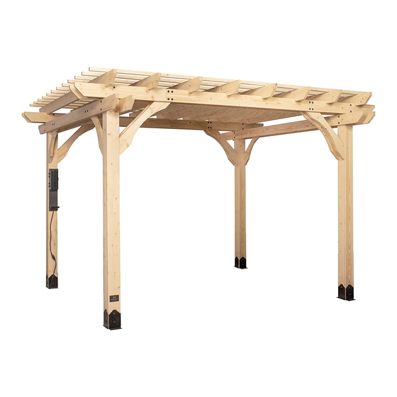
SOMERVILLE 10x14 PERGOLA
MANUFACTURED BY:
Backyard Discovery
3305 Airport Drive
Pittsburg, KS 66762
Model # 2006546
Owner's Manual & Assembly Instructions
800-856-4445
average 2 person assembly time
assembly time may vary based on skill level
For the most up to date assembly manual,
to register your set, or to order replacement parts please visit
www.backyarddiscovery.com
SAVE THIS ASSEMBLY MANUAL FOR FUTURE REFERENCE IN THE EVENT THAT
YOU NEED TO ORDER REPLACEMENT PARTS.
Made in China | INS-2006546-A-SOMERVILLE 10X14 PERGOLA-ENG 10/28/2019
Advertisement

Related Manuals for Backyard Discovery SOMERVILLE 10x14 PERGOLA 2006546


Summary of Contents for Backyard Discovery SOMERVILLE 10x14 PERGOLA 2006546
- Page 1 SOMERVILLE 10x14 PERGOLA MANUFACTURED BY: Backyard Discovery 3305 Airport Drive Pittsburg, KS 66762 Model # 2006546 Owner's Manual & Assembly Instructions 800-856-4445 average 2 person assembly time assembly time may vary based on skill level For the most up to date assembly manual, to register your set, or to order replacement parts please visit www.backyarddiscovery.com...
- Page 2 INSTALLATION SERVICES AVAILABLE! Need a helping hand? Let our team of professionals handle the installation for you! *Installation services are only available to U.S. customers. With Go Con gure, we bring you 18 years of experience right to your doorstep. We service a wide array of indoor and outdoor recreation products that most consumers don’t have the time or ability to deliver &...
- Page 3 Owner’s Manual Please Read This Before Starting Assembly MISSING A PART? CALL US BEFORE GOING BACK TO THE STORE The store where you made your purchase does not stock parts for this item. If you have assembly questions or you are missing or have damaged parts, please call 1-800-856-4445 you can also visit www.backyarddiscovery.com...
- Page 4 Botanical, Adventure Playsets, and Leisure Time Products. Backyard Discovery warrants that this product is free from defect in materials and workmanship for a period of one (1) year from the original date of purchase. This one (1) year warranty covers all parts including wood, hardware, and accessories. All wood carries a ve (5) year pro-rated warranty against rot and decay. Refer to the schedule below for charges associated with replacement of parts under this Limited Warranty.
- Page 5 Owner’s Manual Safety Warnings and Maintenance Instructions WARNING IT IS IMPORTANT TO CHECK AND TIGHTEN ALL HARDWARE AT THE BEGINNING AND DURING THE SEASON AS THEY MAY LOOSEN DUE TO WOOD EXPANSION AND CONTRACTION. • DO NOT climb or walk on the roof for any reason •...
- Page 6 About Our Wood Backyard Discovery uses 100% Cedar (C. Lanceolata) wood. Although we take great care in selecting the best quality lumber available, wood is still a product of nature and susceptible to weathering which can change the appearance of your set.
- Page 7 Owner’s Manual Assembly Tips Protrusion Hazard Incorrect Correct If you see exposed threads and your bolt protrudes beyond the T-Nut you may have over tightened the bolt or used incorrect hardware. If you’ve overtightened, remove the bolt and add washers to eliminate the protrusion.
-
Page 8: Assembly Tip
Owner’s Manual Assembly Tips ASSEMBLY TIP: Keep and eye out for these boxes which will contain helpful pictures and information making the assembly process as quick and painless as possible. Sorting Wood When removing the wood from the boxes we recommend arranging them by part number before you begin assembly. - Page 9 Owner's Manual Tools Required for Installation...
- Page 10 Owner's Manual Basic Setup Dimensions & Assembly Notes It is critically important that you start with square and level footings, concrete pad or deck to attach your structure • Pay close attention to the items needed for each step. Make sure you are using the correct hardware for each step. Using incorrect hardware may result in improper assembly.
-
Page 11: Parts Identification
Owner's Manual Parts Identification Wood Components (Not to Scale) JOIST - W4L13476 1 3/8"x5 1/4"x95 1/4" (36x134x2420) (x2) JOIST - W4L13485 1 3/8"x5 1/4"x95 1/4" (36x134x2420) (x2) JOIST END - W4L13492 1 3/8"x5 1/4"x39 3/4" (36x134x1008) (x2) JOIST END - W4L13475 1 3/8"x5 1/4"x39 3/4"... - Page 12 Owner's Manual Parts Identification Wood Components (Not to Scale) SHORT ANGLE BRACE - W4L13483 LONG ANGLE BRACE - W4L13482 1 3/8"x5 1/4"x29 3/4" (36x134x755) 1 3/8"x5 1/4"x37 1/8" (36x134x942) (x4) (x8) SLOTTED JOIST - W4L13478 1 3/8"x5 1/4"x114" (36x134x2896) (x8) CORD COVER - W4L13486 (x1) 1"x5 1/4"x43 5/8"...
- Page 13 Parts Identification Owner's Manual Wood Components (Not to Scale) PERGOLA POST - W2A03006 5 1/2"x5 1/2"x89 1/2" (140x140x2273) (x2) PERGOLA POST - W2A03008 5 1/2"x5 1/2"x89 1/2" (140x140x2273) (x2)
-
Page 14: Hardware Components
Owner's Manual Parts Identification Hardware Components H100196 BOLT WH BLK (x26) 5/16x7-1/4 H100205 BOLT WH BLK H100193 NUT BARREL WH BLK H100192 NUT BARREL WH BLK (x42) 5/16x2-1/4 (x26) (x42) 5/16x1-1/2 5/16x7/8 H100204 LAG SCREW WH BLK (x18) 5/16x5 1/2 H100206 LAG SCREW WH BLK (x13) - Page 15 Owner's Manual Parts Identification Hardware Components A100042 TORX BIT (x2) T-40 A100041 TORX WRENCH (x2) T-40 H100764 SCREW SETTER (x1)
- Page 16 Owner's Manual Parts Identification Accessory Components (Not to Scale) A6P00173 STAIN MARKER (x1) A100029 FOOT 142 SQUARE POST (x4) A100314 A100241 "A" REVISION TAG BYD ID TAG (SMALL) WITHOUT AGES (x1) (x1) A6P00265 5' PERGOLA ELECTRICAL OUTLET ASSEMBLY (x1)
- Page 17 STEP 1 PERGOLA POST - W2A03006 JOIST - W4L13477 JOIST END - W4L13494 1 3/8"x5 1/4"x90" (36x134x2286) (x2) 5 1/2"x5 1/2"x89 1/2" (140x140x2273) 1 7/16"x5 1/4"x17 3/4" (36x134x451) (x2) (x4) JOIST - W4L13479 JOIST END - W4L13474 PERGOLA POST - W2A03008 1 3/8"x5 1/4"x90"...
- Page 18 STEP 2 JOIST - W4L13485 1 3/8"x5 1/4"x95 1/4" (36x134x2420) (x2) JOIST END - W4L13492 JOIST END - W4L13484 LONG ANGLE BRACE - W4L13482 1 3/8"x5 1/4"x39 3/4" (36x134x1008) (x2) (x2) 1 3/8"x5 1/4"x39 3/4" (36x134x1008) 1 3/8"x5 1/4"x37 1/8" (36x134x942) (x4) H100205 BOLT WH BLK...
- Page 19 STEP 3 JOIST - W4L13476 1 3/8"x5 1/4"x95 1/4" (36x134x2420) (x2) JOIST END - W4L13475 JOIST END - W4L13491 LONG ANGLE BRACE - W4L13482 (x2) 1 3/8"x5 1/4"x39 3/4" (36x134x1008) (x2) 1 3/8"x5 1/4"x39 3/4" (36x134x1008) 1 3/8"x5 1/4"x37 1/8" (36x134x942) (x4) H100205 BOLT WH BLK...
- Page 20 STEP 4 OUTER JOIST ASSEMBLY (x2) FROM PREVIOUS STEPS UPRIGHT ASSEMBLY (x2) FROM PREVIOUS STEPS INNER JOIST ASSEMBLY (x2) FROM PREVIOUS STEPS H100196 BOLT WH BLK H100206 LAG SCREW WH BLK (x8) 5/16x7-1/4 (x8) 5/16x3 H100198 WASHER LOCK EXT BLK H100199 WASHER LOCK EXT BLK H100193...
- Page 21 STEP 5 SLOTTED JOIST - W4L13478 1 3/8"x5 1/4"x114" (36x134x2896) (x8) H100204 H100198 LAG SCREW WH BLK WASHER LOCK EXT BLK (x16) 5/16x5 1/2 (x16) 8x19 NOTES: LOCATE AND USE PILOT HOLES IN REPEAT ON OPPOSITE END AND ON ALL JOISTS THE OUTER JOISTS TO MOUNT D13 BOARDS AS SHOWN.
- Page 22 STEP 6 PURLIN - W4L13480 1 3/8"x1 3/8"x69 5/8" (36x36x1768) (x12) H100201 SCREW PFH BLK (x96) 8x2-1/2 PURLIN - W4L13481 1 3/8"x1 3/8"x90 1/4" (36x36x2291) (x12) (x96) SCREW - 2 1/2" ANGLE CUT PURLIN ANGLE CUT PURLIN (x12) PURLIN (x12) PURLIN NOTES: ASSEMBLE P01 &...
- Page 23 STEP 7 CORD COVER - W4L13486 1"x5 1/4"x43 5/8" (24x134x1109) (x1) A6P00265 H100201 SCREW PFH BLK 5' PERGOLA ELECTRICAL OUTLET ASSEMBLY (x1) (x10) 8x2-1/2 CORD COVER - W4L13487 1"x2 3/8"x7 7/8" (24x60x201) (x1) PRESS THE ELECTRICAL CORD ASSEMBLY INTO THE CUT OUTS ON THE D14 CORD COVER, AS SHOWN.
- Page 24 STEP 8 A100029 FOOT 142 SQUARE POST (x4) NOTES: DECIDE WHERE TO PLACE THE PERGOLA. NOTE THIS MOUNTING PROCEDURE IS MEANT TO BE USED ON CONCRETE ONLY. PLACE THE PERGOLA EXACTLY WHERE IT WILL BE ANCHORED WHEN COMPLETED AND SLIDE A FOOT UNDER EACH POST.
- Page 25 STEP 9 NOTES: USE CHALK TO TRACE AROUND THE EDGES OF EACH FOOT TO MARK THE FEET LOCATIONS.
- Page 26 STEP 1 0 H100120 SCREW CONCRETE ANCHOR (x16) 1/4x2 NOTES: MOVE THE PERGOLA ASIDE AND PLACE EACH FOOT INSIDE THE LINES DRAWN IN THE PREVIOUS STEP. NOW, USE A 3/16" CONCRETE DRILL BIT TO DRILL PILOT HOLES INTO THE CONCRETE PAD. NEXT, USE THE PROVIDED CONCRETE ANCHORS TO ATTACH EACH FOOT TO THE CONCRETE SURFACE.
- Page 27 STEP 11 H100200 SCREW PFH BLK (x16) 8x1 1/2 NOTES: MOVE THE PERGOLA BACK INTO PLACE, SETTING EACH POST INSIDE A FOOT AND MOUNT AS SHOWN USING THE PROVIDED HARDWARE. (x4) SCREW - 1 1/2" REPEAT ON ALL POSTS...
- Page 28 STEP 12 H100392 SCREW PWH BLK (x4) A100314 8x3/4 A100241 "A" REVISION TAG BYD ID TAG (SMALL) WITHOUT AGES (x1) (x1) NOTES: CENTER THE REVISION TAG AND ID TAG ON THE POST AND CENTER VERTICALLY APPROX. 4-1/2" FROM THE GROUND. (x1) BYD ID TAG (SMALL) WITHOUT AGES (x2)
Need help?
Do you have a question about the SOMERVILLE 10x14 PERGOLA 2006546 and is the answer not in the manual?
Questions and answers