Table of Contents
Advertisement
Quick Links
Advertisement
Table of Contents

Subscribe to Our Youtube Channel
Related Manuals for Vents VPA100-1.8-1


Summary of Contents for Vents VPA100-1.8-1
- Page 1 OPERATING MANUAL Ventilation supply unit V29-1_EN-03.indd 1 18.10.2016 10:38:45...
-
Page 2: Table Of Contents
Automated VPA Introduction ........................Designation ........................Delivery set ........................Protection rate ........................ Diagram of design letters .................... Basic parameters and dimensions ................Safety requirements ..................... Design and operation principle ................. Mounting ......................... Connection to electric network ................. External devices ......................VPA control ........................ -
Page 3: Introduction
INTRODUCTION This operating manual is joined with technical description, operation instruction and technical certificate for Ventilation Intake Unit (hereinafter referred to as «VPA») and contains information concerning the mounting, rules and warnings essential for proper and safety VPA operation. Prior to commencement of operation, carefully read this manual and observe the instructions given in it. -
Page 4: Protection Rate
Example of design letters: Ventilation input unit VPA, diameter of connecting tubes 150 mm, heater power 6.0 kW, phase connection: «VENTS VPA 150-6.0-3» BASIC PARAMETERS AND DIMENSIONS Basic technical parameters correspond to values shown in table 1. Overall and mounting dimensions are shown in table 2 and in fig. - Page 5 Table 1 100- 125- 150- 150- 150- 150- 200- 200- 200- 1.8-1 2.4-1 2.4-1 3.4-1 5.1-3 6.0-3 3.4-1 5.1-3 6.0-3 Voltage [V / 50 Hz] 1~ 230 1~ 230 3~ 400 1~ 230 3~ 400 Maximum fan power [W] Fan current [A] 0.32 0.33 0.43...
- Page 6 Automated VPA Table 2 Max. dimensions, mm Type VPA 100… 421.5 VPA 125… 421.5 VPA 150… 496.5 VPA 200… 526.5 VPA 250… 526.5 VPA 315… 566.5 Fig. 1 V29-1_EN-03.indd 6 18.10.2016 10:38:47...
-
Page 7: Safety Requirements
SAFETY REQUIREMENTS During installation and operation of VPA, there must be fulfilled the requirements of this operating manual, «Electric installations arrangement rules», «Rules of consumers» electric installations technical operation», «Rules of consumers» electric installations safe operation», valid construction codes, and «Rules of fire safety in Ukraine» as well. VPA relates to electric equipment and, therefore, it is necessary to observe the safety rules concerning the electric equipment handling. -
Page 8: Design And Operation Principle
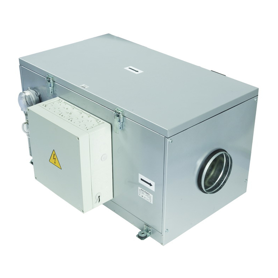
Automated VPA DESIGN AND OPERATION PRINCIPLE VPA provides controlling the air flow rate, air temperature (preheating) and to filter it as well. VPA exterior view is shown in fig. 2. Inside the case 1 there is installed the centrifugal-axial fan 2 equipped with the motor with external rotor and integrated thermal protection. - Page 9 Fig. 2 V29-1_EN-03.indd 9 18.10.2016 10:38:49...
-
Page 10: Mounting
Automated VPA VPA shall be mounted by qualified person or company properly trained and having the required tools and materials. MOUNTING VPA shall be mounted in such way that the arrow on the cover coincides with air flow direction in the system and there is the sufficient space for access for maintenance, service or replacement. -
Page 11: Connection To Electric Network
PRIOR TO ANY WORKS IN VPA, IT MUST BE DISCONNECTED FROM THE POWER SUPPLY AND THE POWER SWITCH SHOULD BE IN «O» POSITION (SWITCHED-OFF)! CONNECTING TO ELECTRIC NETWORK Depending on VPA type, 230 V / 50 Hz AC or 400 V / 50 Hz AC power supply is used. Connecting VPA to electric network is performed by the qualified electrician only. - Page 12 Automated VPA Unit Fig. 4 Unit Fig. 5 QF — external switch with thermal-magnetic tripper (circuit-breaker), X1 — terminal box for connecting the electric network wires and external devices: sensors, shutter drive, control panel, etc. Circuit-breaker QF shall be located in a manner which ensures free access to it for the unit operative shutoff.
- Page 13 Cross-section area values in table 3 are guiding only! While selecting the cross-section area, take into consideration the wire maximum allowable heating dependent on the maximum current, the wire length and its location (air, wall). Table. 3 Copper cable Type Circuit-breaker single-phase three-phase...
-
Page 14: External Devices
Automated VPA EXTERNAL DEVICES Control panel structurally is integrated with the room temperature sensor in single case and, therefore, while installing the control panel position it in operating zone but not closer than at 1 m from the heating devices, doors and windows. Control panel is mounted on a wall with the help of supplied screws. - Page 15 Channel temperature sensor Channel temperature sensor is mounted at distance not less than 2 m from the VPA output tube in place where the heated air intensive flow with balanced temperature around the sensor is ensured (fig. 6). The channel sensor is connected to control unit with the help of supplied cable 4 m long. The contacts X1:8 and X1:9 (polarity is indifferent) located in the terminal block are used for channel temperature sensor connection.
- Page 16 Automated VPA Differential pressure sensor Characteristic Operating pressure range: 500 - 500 kPa Max. operating pressure: 5.0 kPa within the entire range Temperature range: 0 °C to + 85 °C Electric load: max. 1.5 A (0.4 A / 250 V AC Electric protection: IP 54 with protective cover Differential pressure sensor is supplied previously installed on VPA case.
- Page 17 Control unit for single phase electric network 230 V / 50 Hz Cover is not shown Fig. 7 V29-1_EN-03.indd 17 18.10.2016 10:38:51...
- Page 18 Automated VPA Terminal block X1 Terminal Circuit External connection marking Network ~ 230 V Network ~ 230 V Protective earthing Protective earthing Motor - phase Motor - zero +10V Motor control circuit Motor control circuit Motor control circuit BP1-1 Differential pressure sensor BP1-2 Differential pressure sensor RK1-1...
- Page 19 Control unit for single phase electric network 400 V / 50 Hz Cover is not shown Fig. 8 V29-1_EN-03.indd 19 18.10.2016 10:38:52...
- Page 20 Automated VPA Terminal block X1 Terminal Circuit External connection marking Network ~ 400 V Network ~ 400 V Network ~ 400 V Neutral Protective earthing Protective earthing Motor - phase Motor - zero +10V Motor control circuit Motor control circuit Motor control circuit BP1-1 Differential pressure sensor...
- Page 21 Connecting the external devices contacts X1:8, X1:9 for channel temperature sensor connection contacts X1:17, X1:18 for connecting the automatic ire extinguishing circuit signal contacts X1:19, X1:20 for hygrostat connection contacts X1:10, X1:11, X1:12, X1:13 for control panel connection Fig. 9 V29-1_EN-03.indd 21 18.10.2016 10:38:52...
-
Page 22: Vpa Control
Automated VPA VPA CONTROL VPA control is carried out by means of remote control panel. Physical channel for «panel-unit» communication is realized using the standard four- core cable. Data exchange is executed in digital form on basis of RS-485 standard. Functional capabilities The system allows controlling the intake air capacity and has 3 steps of rotation speed. -
Page 23: Control Panel
CONTROL PANEL Fig. 10 1. Graphical indicator. 2. Red LED signals the emergency situation occurrence or faulty (lights) or need to replace the filter (flashes). 3. Temperature sensor. 4. «Up» button — selecting position in menu (cursor moves upwards) or decreasing the current parameter. -
Page 24: Switching-On And Switching-Off Vpa
Automated VPA SWITCHING-ON AND SWITCHING-OFF VPA Turn the VPA power switch to position «1»; logo VENTS is displayed on indicator — de- energized status of unit. To switch-on the VPA it is necessary to press Power button; menu of the VPA current status selection (On/Off) menu is displayed on indicator. Required option is selected by sequential pressing the «Power»... - Page 25 Pressing the Escape button allows switching to interface language selection mode. Language selection is carried out using the Up/Down buttons. The language change is executed at pressing the Enter button. If during 10 seconds no button is pressed, as well as at pressing the Escape button, the switching to main operating window without changing the interface language occurs.
- Page 26 Automated VPA «Fan speed» This parameter allows changing the value of fan speed (Up/Down buttons). Service menu allows to user to enable and set the «service» functions: «Clock and calendar» Date and time setup is required for correct operation of the «day timer» and the «week timer».
- Page 27 Selection of the changed position (Year, Month, Day, Day of week, Hours, Minutes) is carried out using the Enter button. Change of the selected position is carried out using the Up/Down buttons. «Filter replacement timer» Allows to user to determine the time interval after which the control panel will be switched to «reminding mode»...
- Page 28 Automated VPA Table containing the reminder periodically (for short time period) substitutes for the «main operating window»; the red LED is flashing. To disable the reminder it is necessary to enter into «timer of filter replacement» menu and press the Enter button. The following reminder will appear in time interval set by the user.
- Page 29 Selection of changed position (switching-on time, switching-off time, Hours, Minutes) is carried out using the Enter button. Change of the selected position value is carried out using the Up/Down buttons. «Week timer» This parameter allows to user to set the program of VPA operation for any day of week. After activation of this mode, VPA will automatically (according to set parameters) change the fan speed and temperature of governing at set time of set days of week.
- Page 30 Automated VPA Selection of changed position (day of week, ON/Off state of timer on given day of week, time period of the unit operation in given mode, temperature of governing, fan speed) is carried out using the Enter button. Change of the selected position value is carried out using the Up/Down buttons. «Seasonal mode»...
-
Page 31: Emergency Situations
VPA is switched-off In 2 minutes. EMERGENCY SITUATION In case of operation of one from two (either) sensor-thermal switch of the tubular electric heating elements, as well as at filter clogging (operation of the differential pressure) or communication line fault, the unit is switched to emergency shutoff mode «tubular electric heating elements blowing»... - Page 32 Automated VPA Perform the following actions in case of emergency situations: Disconnect VPA from the power source (turn the switch to «0» position); wait for VPA fan complete stop; open and check the heater and filter, remove the emergency shutoff cause; remove the control unit cover and check the safety devices, replace the faulty devices by the new ones with the same parameters;...
-
Page 33: Manufacture΄s Warranty
STORAGE AND TRANSPORTATION RULES VPA should be stored in the factory package in well ventilated dry premise at temperature of - 5 °C to + 40 °C. Presence of the fumes and impurities in the air, leading to corrosion and breaking the insulation and fittings sealing, is not admitted. -
Page 34: Acceptance Certificate
Automated VPA MANUFACTURER is not responsible for damages resulting from VPA misuse or gross mechanical intervention. VPA owner must follow the guidelines. ACCEPTANCE CERTIFICATE Ventilation inlet unit «VPA_______» complies with technical requirements and is judged as ready for operation. Acceptor mark Release date Seller Name of trading organization, shop stamp... -
Page 35: Commissioning Certificate
COMMISSIONING CERTIFICATE Ventilation inlet unit «VPA_______» is connected to electric network according to requirements of this Operating Manual by specialist: Name_____________________________________________________________________ Date______________________ Signature_________________________________ __________________________________________________________________________ __________________________________________________________________________ __________________________________________________________________________ __________________________________________________________________________ WARRANTY CARD _____________________________________________________________ _____________________________________________________________ _____________________________________________________________ _____________________________________________________________ _____________________________________________________________ _____________________________________________________________ _____________________________________________________________ _____________________________________________________________ ___________________________________________ V29-1EN-03 V29-1_EN-03.indd 35 18.10.2016 10:38:54... - Page 36 V29-1EN-03 V29-1_EN-03.indd 36 18.10.2016 10:38:54...
Need help?
Do you have a question about the VPA100-1.8-1 and is the answer not in the manual?
Questions and answers