Table of Contents
Advertisement
Quick Links
Advertisement
Table of Contents

Subscribe to Our Youtube Channel
Related Manuals for Vents VN Series


Summary of Contents for Vents VN Series
- Page 1 CENTRIFUGAL EXTRACT FAN User’s manual www.ventilation-system.com...
-
Page 2: Table Of Contents
CONTENTS Purpose ..................................................2 Brief description ..............................................8 Delivery set ................................................9 Designation key ..............................................10 Operation guidelines ............................................12 Mounting and set-up ............................................13 Electronics operation algorithm ....................................... 17 Timer and humidity sensor adjustment ....................................18 Connection to power mains ........................................19 Technical maintenanance .......................................... - Page 3 This unit is not intended for use by persons (including children) with reduced physical, sensory or mental capabilities, or lack of experience and knowledge, unless they have been given supervision or instruction concerning use of the unit by a person responsible for their safety.
- Page 4 Connection to the mains must be made through a disconnecting device, which is integrated into the fixed wiring system in accordance with the wiring rules for design of electrical units, and has a contact separation in all poles that allows for full disconnection under overvoltage category III conditions.
- Page 5 All operations described in this manual must be performed by qualified personnel only, properly trained and qualified to install, make electrical connections and maintain ventilation units. Do not attempt to install the product, connect it to the mains, or perform maintenance yourself. This is unsafe and impossible without special knowledge.
- Page 6 Transported air must not contain any dust or other solid impurities, sticky substances, or fibrous materials. Do not use the unit in a hazardous or explosive environment containing spirits, gasoline, insecticides, etc. Do not close or block the intake or extract vents in order to ensure the efficient air flow.
- Page 7 Do not sit on the unit and do not put objects on it. The information in this user’s manual was correct at the time of the document’s preparation. The Company reserves the right to modify the technical characteristics, design, or configuration of its products at any time in order to incorporate the latest technological developments.
-
Page 8: Brief Description
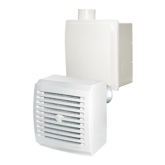
BRIEF DESCRIPTION The product is a double-speed pressure fan for exhaust ventilation of small and medium-sized domestic spaces heated during the cold season. In the base models the fan speed is manually set by means of an external switch. The fan can be mounted to the ceiling or onto a wall with air extraction into a ventilation shaft or a round air duct of a matching diameter. -
Page 9: Delivery Set
DELIVERY SET VNV KP/KV/KVK KV, KP, KVK Fan assembly, pcs Ventilation unit, pcs Casing, pcs Fastener set, pcs Mounting bracket, pcs Cardboard spacer, pcs Plastic screwdriver, pcs (models with timer only) Set of noise-insulated inserts User’s manual, pcs Packing box, pcs... -
Page 10: Designation Key
DESIGNATION KEY VN- 1 A 80 K TR Additional options _ — no default options T — timer TR — user-adjustable timer I — intermittent operation switch H — humidity sensor Fire-safety damper: _ — without fire-safety damper by default K —... - Page 11 VNV - 1 A 80 KP K - L T Additional options _ — no default options T — timer TR — user-adjustable timer I — intermittent operation switch H — humidity sensor Connection of air ducts from another room: _ —...
-
Page 12: Operation Guidelines
Conventional designation of casings for fans KV K - L 80 Spigot diameter Connection of air ducts from another room: _ — not available L — left-hand side R — right-hand side D — bottom side Fire-safety damper: _ — without fire-safety damper by default K —... -
Page 13: Mounting And Set-Up
MOUNTING AND SET-UP The fan can be mounted to the ceiling or onto a wall with air extraction into a ventilation shaft or a round air duct of a matching diameter. The fan mounting example is shown in Fig. 12-22. Through-the-wall installation of fans with an additional inlet pipe is shown on Fig. - Page 14 3.8. Rotate the fan to access the markings, drill the dowel holes and insert the dowels (Fig. 43). 3.9. Rotate the fan and align the mounting holes of the casing and those of the swing damper, and secure the fan with self- tapping screws (Fig.
- Page 15 6.4. Before installing the casing, make sure that the fire retardant spring-loaded non-return valve of the KP 80 casing, which will be installed in the niche, closes in the absence of air flow under the influence of the spring. 6.5. Install the KP 80 casing into the recess and fix it with mortar. Attention! It is not allowed to have gaps between the casing and the hole in the wall.
- Page 16 Location of the backdraft damper in case of ceiling mounting. Use a steel pipe of rectangular cross-section or a spiral-wound air duct for the collective air duct. Use flexible air ducts for the connection duct. The nominal diameter of air duct connections is 80 mm. If the connection air duct is concealed within a brick wall it should be wrapped with self-adhesive PVC tape to prevent mortar-induced corrosion.
-
Page 17: Electronics Operation Algorithm
ELECTRONICS OPERATION ALGORITHM T — with timer The fan is switched on to the 2nd speed manually by an external switch S1 in parallel with the lighting, with a turn-off delay time of 50 seconds. Once the external switch S1 is returned to the initial position the fan shuts down after a 6 minute timer delay. -
Page 18: Timer And Humidity Sensor Adjustment
TIMER AND HUMIDITY SENSOR ADJUSTMENT DO NOT USE A METAL SCREWDRIVER, KNIFE, ETC. FOR ADJUSTMENT OPERATIONS NOT TO DAMAGE THE CIRCUIT BOARD Attention! The control board circuit is live! Disconnect the fan from power supply prior to any adjustment operations. The fan is supplied with a special plastic screwdriver for adjusting the settings. -
Page 19: Connection To Power Mains
CONNECTION TO POWER MAINS To connect the fan to the electric mains: • Run the cable through the gland in the rear part of the casing. • Strip the insulation leaving 7–8 mm long tips. • Remove the control unit cover (Fig. 60-61). •... -
Page 20: Troubleshooting
TROUBLESHOOTING Problem Possible reasons Troubleshooting Make sure the power supply line No power supply. is connected correctly, otherwise When the unit is connected to power mains, the fan does not rotate and troubleshoot the connection error. does not respond to any controls. Internal connection fault. -
Page 21: Manufacturer's Warranty
MANUFACTURER’S WARRANTY The product is in compliance with EU norms and standards on low voltage guidelines and electromagnetic compatibility. We hereby declare that the product complies with the provisions of Electromagnetic Compatibility (EMC) Directive 2014/30/ EU of the European Parliament and of the Council, Low Voltage Directive (LVD) 2014/35/EU of the European Parliament and of the Council and CE-marking Council Directive 93/68/EEC. - Page 22 • Replacement and use of any assemblies, parts and components not approved by the manufacturer. • Unit misuse. • Violation of the unit installation regulations by the user. • Violation of the unit control regulations by the user. • Unit connection to power mains with a voltage different from the one stated in the user's manual. •...
- Page 23 VN 80 VN-1 80/VNV-1 80 BK2...
- Page 24 VN 80 K VN-1 80 K...
- Page 25 VNV-1 80 KV VN-1 80 KP...
- Page 26 VNV-1 80 KVK VNV-1 80...
- Page 27 KP 80 KV 80 KVK 80...
- Page 28 VN 80, VN-1 80, VN 80 K, VN-1 80 K installation options...
- Page 29 VNV-1 80 KV and VNV-1 80 KVK installation options VNV-1 80 KP installation options...
- Page 30 Installation options for fans with an additional inlet spigot Fan placement options relative to walls and ceiling...
- Page 31 VN-1 80 installation steps...
- Page 32 VN 80 installation steps VN-1 80 K installation steps...
- Page 34 VNV-1 80 KV, VNV-1 80 KVK, VNV-1 80 KP installation steps...
- Page 36 Connection of fans A, B, C, D variants E variant...
- Page 37 Wiring diagram of basic fan models A, B, D variants C variant E variant Designation key: L – phase, N – neutral, S – external switch External switch S is used to set the fan to one of the available speeds or disable it manually.
- Page 38 Wiring diagram for fan models with timer, adjustable timer, interval switch or humidity sensor A, B, D variants E variant Designation key: L – phase, N – neutral, LT – line for switching the fan to maximum speed, S, S1, SB – external switch The fan operates at speed 1 when the SB switch is closed or switched off when it is open.
- Page 39 Fan maintenance...
- Page 40 Timer and humidity sensor adjustment DO NOT USE A METAL SCREWDRIVER, KNIFE, ETC. FOR ADJUSTMENT OPERATIONS NOT TO DAMAGE THE CIRCUIT BOARD...
- Page 41 Quality Inspector’s Stamp Sold by (name and stamp of the seller) Manufacture Date Purchase Date...
- Page 44 Certificate of acceptance _______________________________________________ The fan is recognized as serviceable. V22EN-09...
Need help?
Do you have a question about the VN Series and is the answer not in the manual?
Questions and answers