Table of Contents
Advertisement
Quick Links
Advertisement
Table of Contents

Subscribe to Our Youtube Channel
Related Manuals for Vents VPVO


Summary of Contents for Vents VPVO
- Page 1 USER’S MANUAL VPVO Axial pressurisation fan...
-
Page 2: Table Of Contents
Warranty card ....................................19 This user’s manual is a main operating document intended for technical, maintenance, and operating staff. The manual contains information about purpose, technical details, operating principle, design, and installation of the VPVO unit and all its modifications. -
Page 3: Safety Requirements
SAFETY REQUIREMENTS • Please read the user’s manual carefully prior to installing and operating the unit. • All user’s manual requirements as well as the provisions of all the applicable local and national construction, electrical, and technical norms and standards must be observed when installing and operating the unit. - Page 4 VPVO • Do not touch the unit controls • Do not wash the unit with with wet hands. water. • Do not carry out the • Protect the electric parts of the installation and maintenance unit against ingress of water.
-
Page 5: Purpose
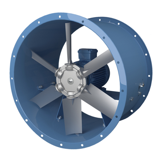
PURPOSE The axial pressurisation fan of VPVO series is used for ventilation of industrial, administrative, residential and other buildings. It is also used for pressurisation of fire-fighting equipment and fresh air supply in case of fire. The fan is intended for general ventilation in systems with high air flow rates. -
Page 6: Designation Key
Impeller Modification V P V O - 6 3 0 K-2 D / 5.5- 8 / 3 5 / A L - U 1 - K VPVO: axial pressurisation fan Standard size (air duct size) [mm] Casing modification: _: standard casing... -
Page 7: Technical Data
Ø d n holes n holes Ø D Ø D Ø D1 Ø D1 Ø D2 Ø D2 DIMENSIONS [MM] MODEL VPVO-400 350, 450 8/12 VPVO-450 350, 450, 550 8/12 VPVO-500 350, 450, 550 12/12 VPVO-560 350, 450, 550, 650... -
Page 8: Unit Design And Operating Principle
VPVO UNIT DESIGN AND OPERATING PRINCIPLE Fan with a casing modi cation without terminal box Fan with a casing modi cation with a terminal box Impeller Impeller Access door Access door Inlet ring VK-VO * Inlet ring VK-VO * Protective mesh... -
Page 9: Mounting And Set-Up
MOUNTING AND SET-UP ALL OPERATIONS DESCRIBED IN THIS USER’S MANUAL MUST BE PERFORMED BY QUALIFIED PERSONNEL ONLY, PROPERLY TRAINED AND QUALIFIED TO INSTALL AND MAINTAIN VENTILATION EQUIPMENT. DO NOT ATTEMPT TO INSTALL THE PRODUCT YOURSELF. IT IS UNSAFE AND IMPOSSIBLE WITHOUT SPECIAL KNOWLEDGE. WHILE INSTALLING THE UNIT ENSURE CONVENIENT ACCESS FOR SUBSEQUENT MAINTENANCE AND REPAIR. - Page 10 VPVO Mounting in case of no ductwork upstream of the fan Obstructed space installation If the ductwork is not available at the fan inlet, the inlet cone VK-VO must To ensure normal operation of the fan in an obstructed space make sure be installed to improve aerodynamic parameters of the air flow.
-
Page 11: Connection To Power Mains
CONNECTION TO POWER MAINS DISCONNECT THE POWER SUPPLY PRIOR TO ANY OPERATIONS WITH THE UNIT. CONNECTION OF THE UNIT TO POWER MAINS IS ALLOWED BY A QUALIFIED ELECTRICIAN WITH A WORK PERMIT FOR THE ELECTRIC UNITS UP TO 1000 V AFTER CAREFUL READING OF THE PRESENT USER’S MANUAL. - Page 12 VPVO ASYNCHRONOUS ELECTRIC MOTOR STARTING METHODS There are several methods for starting asynchronous squirrel-cage electric motors. The most common methods are: direct-on-line (DOL), with a soft starter (SS) or with a frequency converter (FC). Direct-on-line starting In case of direct-on-line starting (i.e. by connecting the motor to the electric mains with a simple line contactor), the motor starting time significantly increases due to high inertia of the impeller, which, in turn, results in high in-rush starting currents in the circuit.
-
Page 13: Commissioning
Problems associated with DOL starting The problems caused by DOL starting may be divided into two groups: An abrupt start causes mechanical shock, jolts in the mechanism, shock removal of free play etc. A heavy start cannot be completed. Let us review three variations of a heavy start: 1. -
Page 14: Technical Maintenance
VPVO TECHNICAL MAINTENANCE DISCONNECT THE UNIT FROM POWER SUPPLY BEFORE ANY MAINTENANCE OPERATIONS! PRIOR TO COMMENCING ANY TECHNICAL MAINTENANCE PUT UP A PROHIBITORY SIGN ON THE FAN STARTING PANEL: “DO NOT SWITCH ON! MEN AT WORK!” AVOID LIQUID SPILLS ON THE MOTOR! DO NOT USE AGGRESSIVE SOLVENTS AND... - Page 15 The fan fails to reach the Fan motor overloaded. Eliminate the overload. required rotation speed due to Improper fan starting method. Use a soft starter or frequency converter to start the motor serious overheating of the fan (see “Asynchronous Electric Motor Starting Methods” motor.
-
Page 16: Storage And Transportation Regulations
VPVO STORAGE AND TRANSPORTATION REGULATIONS • Store the unit in the manufacturer’s original packaging box in a dry closed ventilated premise with temperature range from +5 °C to + 40 °C and relative humidity up to 70 %. • Storage environment must not contain aggressive vapors and chemical mixtures provoking corrosion, insulation, and sealing deformation. -
Page 17: Manufacturer's Warranty
MANUFACTURER’S WARRANTY The product is in compliance with EU norms and standards on low voltage guidelines and electromagnetic compatibility. We hereby declare that the product complies with the provisions of Electromagnetic Council Directive 2014/30/EU, Low Voltage Directive 2014/35/ EU and CE-marking Directive 93/68/EEC. This certificate is issued following test carried out on samples of the product referred to above. The manufacturer hereby warrants normal operation of the unit for 24 months after the retail sale date provided the user's observance of the transportation, storage, installation, and operation regulations. - Page 18 VPVO www.ventilation-system.com...
-
Page 19: Acceptance Certificate
This is to certify acceptance of the complete unit delivery with the user’s manual. The warranty terms are acknowledged and accepted. Customer’s Signature Seller’s Stamp INSTALLATION CERTIFICATE The VPVO _______________________ unit is installed pursuant to the requirements stated in the present user's manual. Company name Address Phone Number Installation Technician’s Full Name... - Page 20 V118EN-05...
Need help?
Do you have a question about the VPVO and is the answer not in the manual?
Questions and answers