Table of Contents
Advertisement
Quick Links
Advertisement
Table of Contents

Related Manuals for Vents VP Series


Summary of Contents for Vents VP Series
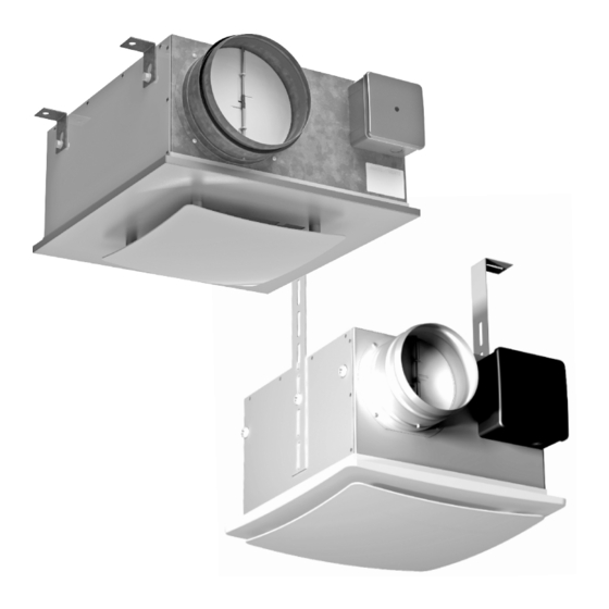
- Page 1 USER'S MANUAL CEILING FAN VP SERIES...
-
Page 2: Table Of Contents
CONTENTS р. 3 Purpose р. 3 Delivery set р. 3 Designation key р. 4 Technical data р. 5 Safety requirements р. 5 Fan design р. 6 Mounting and operation guidelines р. 9 Connection to power mains р. 9 Technical maintenance р. -
Page 3: Purpose
PURPOSE The VP ceiling fan in a metal casing with 100, 125 and 150 mm exhaust outlets (hereinafter "Fan") is intended for ventilation systems of industrial or residential buildings, swimming pools, blocks of flats, offices, hospitals, restaurants and other spaces heated during the winter. The air discharged by the fan must not contain dust, solids, sticky substances and fibrous materials. -
Page 4: Technical Data
TECHNICAL DATA The names of the fans, their parameters and connecting dimensions are given in tables 1, 2. Figure 1.1 Figure 1.2 VP 125 K VP 150 K VP 125 K Q Fan type VP 100 K Q VP 100 K Voltage [V] Frequency [Hz] Power [W]... -
Page 5: Safety Requirements
SAFETY REQUIREMENTS Disconnect the fan from power mains prior to any installation, setup, maintenance and repair operations. The fan must be connected by an expert qualified for unassisted operations with electrical installations up to 1,000 V after being made familiar with the present technical certificate. Prior to installation check for any visible damage to the impeller, casing and grille. - Page 6 INSTALLATION AND OPERATION INSTRUCTIONS The fan is installed between the floor slab and the suspended ceiling by means of two mounting brackets. The distance between the bracket attachment point and the suspended ceiling must be within 165 - 390 mm. The fan installation steps are given in Fig.
- Page 7 VP 100 K Q, VP K VP 125 K Q, VP 125 K 280 mm Figure 5...
- Page 8 VP 150 K 250 mm 403,5 mm Figure 6...
-
Page 9: Connection To Power Mains
CONNECTION TO POWER MAINS Disconnect the damper from the power supply (electric mains) prior to any work on the unit. Power mains connection shall only be performed by a qualified electrician. The nominal electrical parameters of the fan are given on the manufacturer's label. Any tampering with the internal connections is prohibited and will void the warranty. - Page 10 The electrical connections are terminated on the terminal block located inside the fan casing in accordance with the Wiring Diagram and the terminal designations (Fig. 7). The terminal designation diagram is given on a label inside the terminal box. ~230 V РЕ...
- Page 11 Figure 9...
-
Page 12: Manufacturer's Warranty
Take the necessary measures to prevent penetration of smoke, carbon monoxide and other combustion products into the spaces through open smoke ducts or other fire-safety infrastructure as well as prevent back flow of gases from any appliances which produce gas flame or naked flame. - Page 13 The warranty is exclusively limited to the defects of workmanship. Any and all defects and malfunctions including mechanical damage caused by physical contact in the course of operation or natural wear and tear shall not be deemed warranty cases. The warranty liabilities shall not cover any malfunctions resulting from disregard of the instructions specific to the operation, care and maintenance of the unit or any unauthorised alterations and modifications to the unit design made by the user or any third party.
-
Page 14: Acceptance Certificate
ACCEPTANCE CERTIFICATE СВИДЕТЕЛЬСТВО О ПРИЕМКЕ CEILING FAN Unit Type VP ____________ Model Serial Number Manufacture Date is compliant with the technical specifications and is hereby declared ready for service. We hereby declare that the product complies with the essential protection requirements of Electromagnetic Council Directive2004/108/EC, 89/336/EEC and Low Voltage Directive 2006/95/EC, 73/23/EEC and CE-marking Directive 93/68/EEC on the approximation of the laws of the Member States relating to electromagnetic compatibility. -
Page 15: Warranty Card
WARRANTY CARD WARRANTY CARD Unit Type CEILING FAN Model VP _________ Serial Number Purchase Date Purchase Date Warranty Period Seller's Stamp Seller... - Page 16 V69EN-03...
Need help?
Do you have a question about the VP Series and is the answer not in the manual?
Questions and answers