Advertisement
Advertisement
Table of Contents

Subscribe to Our Youtube Channel
Related Manuals for FuzzDog Blaster!


Summary of Contents for FuzzDog Blaster!
- Page 1 Blaster Clone of the Alembic Stratoblaster boost PedalParts.co.uk...
- Page 2 Schematic 10u tantalum 100R (68K*) 1u5 tantalum 100u electrolytic 100K JFET (2N5457, J201) 2K2 (CLR) 50KB (50KC**) *Original value - smaller value is less intrusive. ** Reverse log gives better control if you can get it...
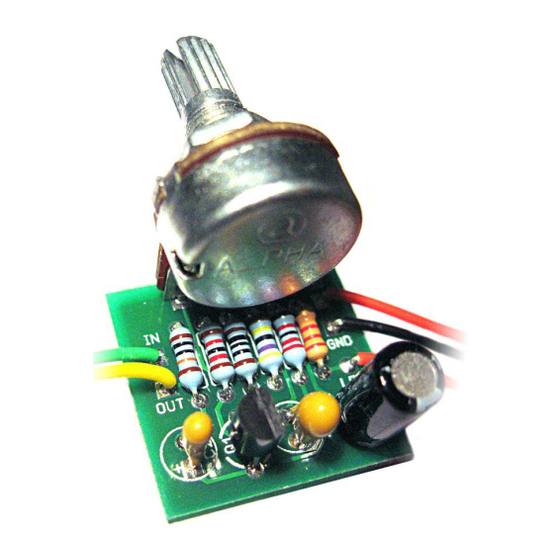
- Page 3 The PCB is designed to have the boost pot mounted directly. You can use wire if you like - simply connect the board pads to the corresponding pins on the pot. Wiring shown overleaf will disconnect the battery when you remove the jack plug from the input, and also when a DC plug is inserted.
- Page 4 Test the board! A A T Once you’ve finished the circuit it makes sense to test is before starting on the switch and LED wiring. It’ll cut down troubleshooting time in the long run. If the circuit works at this stage, but it doesn’t once you wire up the switch - guess what? You’ve probably made a mistake with the switch.
- Page 5 Wire it up BOARD BOARD INPUT BOARD BOARD BOARD BOARD LED+ BOARD BOARD BATTERY The Board GND connections don’t all have to directly attach to the board. You can run a couple of wires from the DC connector, one to the board, another to the IN jack, then daisy chain that over to the OUT jack.
Need help?
Do you have a question about the Blaster! and is the answer not in the manual?
Questions and answers