
Related Manuals for Stahl 9143 Series


Summary of Contents for Stahl 9143 Series
- Page 1 Betriebsanleitung Additional languages r-stahl.com Ex i Stromversorgung Reihe 9143...
-
Page 2: Table Of Contents
Inhaltsverzeichnis Allgemeine Angaben ...................3 Hersteller ......................3 Angaben zur Betriebsanleitung ................3 Weitere Dokumente ....................3 Konformität zu Normen und Bestimmungen ............3 Erläuterung der Symbole ..................4 Symbole in der Betriebsanleitung ...............4 Warnhinweise .....................4 Symbole am Gerät ....................5 Sicherheitshinweise ....................5 Aufbewahrung der Betriebsanleitung ..............5 Qualifikation des Personals ................5 Sichere Verwendung ...................6 Umbauten und Änderungen ................7... -
Page 3: De De
Diese ist rechtsverbindlich in allen juristischen Angelegenheiten. Weitere Dokumente • Installationsanleitung Schaltschrank • Datenblatt Dokumente in weiteren Sprachen, siehe r-stahl.com. Konformität zu Normen und Bestimmungen Zertifikate und EU-Konformitätserklärung, siehe r-stahl.com. Das Gerät verfügt über eine IECEx-Zulassung. Zertifikat siehe IECEx-Homepage: http://iecex.iec.ch/ Weitere nationale Zertifikate stehen unter dem folgenden Link zum Download bereit: https://r-stahl.com/de/global/support/downloads/. -
Page 4: Erläuterung Der Symbole
Erläuterung der Symbole Erläuterung der Symbole Symbole in der Betriebsanleitung Symbol Bedeutung Tipps und Empfehlungen zum Gebrauch des Geräts Gefahr durch explosionsfähige Atmosphäre Gefahr durch spannungsführende Teile Warnhinweise Warnhinweise unbedingt befolgen, um das konstruktive und durch den Betrieb bedingte Risiko zu minimieren. Die Warnhinweise sind wie folgt aufgebaut: •... -
Page 5: Symbole Am Gerät
Normen und Bestimmungen umfasst. Für Tätigkeiten in explosionsgefährdeten Bereichen sind weitere Kenntnisse erforderlich! R. STAHL empfiehlt einen Kenntnisstand, der in folgenden Normen beschrieben wird: • IEC/EN 60079-14 (Projektierung, Auswahl und Errichtung elektrischer Anlagen) • IEC/EN 60079-17 (Prüfung und Instandhaltung elektrischer Anlagen) •... -
Page 6: 3.3 Sichere Verwendung
• Bei Betriebsbedingungen, die durch die technischen Daten des Geräts nicht abgedeckt werden, unbedingt bei der R. STAHL Schaltgeräte GmbH rückfragen. • Sicherstellen, dass das Gerät unbeschädigt ist. • Für Schäden, die durch fehlerhaften oder unzulässigen Einsatz des Geräts sowie durch Nichtbeachtung dieser Betriebsanleitung entstehen, besteht keine Haftung. -
Page 7: Umbauten Und Änderungen
Funktion und Geräteaufbau Inbetriebnahme, Wartung, Reparatur • Inbetriebnahme und Instandsetzung nur durch qualifizierte und autorisierte Personen (siehe Kapitel "Qualifikation des Personals") durchführen lassen. • Vor Inbetriebnahme sicherstellen, dass das Gerät unbeschädigt ist. • Nur Wartungsarbeiten durchführen, die in dieser Betriebsanleitung beschrieben sind. •... -
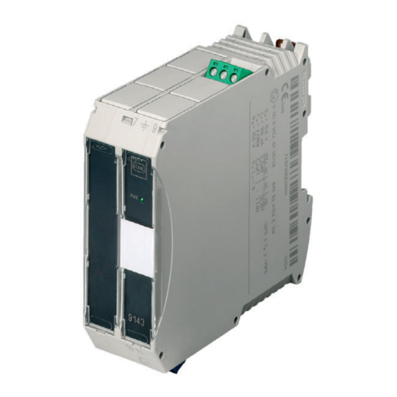
Page 8: 4.2 Geräteaufbau
Technische Daten Geräteaufbau Gerätelement Beschreibung Grüne Klemmen Anschlussklemme für den sicheren Bereich LED "PWR", grün Anzeige Hilfsenergie Blaue Klemmen Anschlussklemmen für den Ex-Bereich (eigensicher Ex i) 9143 09061E00 Technische Daten Kennzeichnung Typbezeichnung 9143/10-…-…-.0 CE-Kennzeichnung 0158 Explosionsschutz Ausführung 9143/10-...-...-10 9143/10-...-...-20 Global (IECEx) Gas, Staub und IECEx BVS 12.0009X IECEx BVS 12.0009X... - Page 9 Technische Daten Explosionsschutz Ausführung 9143/10-065- 9143/10-099- 9143/10-104- 9143/10-114- 200-.0 220-.0 220-.0 200-.0 Sicherheitstechnische Daten Max. Spannung U 6,5 V 9,9 V 10,4 V 11,4 V Max. Strom I 200 mA 220 mA 220 mA 200 mA Max. Leistung P 1,3 W 2,178 W 2,288 W 2,28 W...
- Page 10 Technische Daten Ausführung 9143/10-...-...-10 9143/10-...-...-20 Elektrische Daten Hilfsenergie Nennspannung 24 V AC / DC 110 / 115 / 230 V AC Spannungs- AC: 20 ... 28 V 85 ... 253 V AC bereich DC: 18 ... 35 V Frequenzbereich AC: 48 ... 62 Hz 48 ...
- Page 11 10597E01 24 V AC / DC Sicherer Bereich Ex - Bereich Typ 9143/..-... pac-Bus Zone 1 Zone 2 -...-10. Feldgerät ISpac Trennstufe SPS / PLS 10598E01 Weitere technische Daten, siehe r-stahl.com. 159855 / 9143601310 Ex i Stromversorgung 2020-12-04·BA00·III·de·14 Reihe 9143...
-
Page 12: Projektierung
• Schaltschrank so aufbauen und einrichten, dass er immer innerhalb des zulässigen Temperaturbereichs betrieben wird. • "Installationsanleitung Schaltschrank" sorgfältig beachten. Detaillierte Angaben zur Projektierung finden Sie in der "Installationsanleitung Schaltschrank" (Download über r-stahl.com, Produktdokumentation, Unterpunkt "Projektierung"). Transport und Lagerung • Gerät nur in Originalverpackung transportieren und lagern. -
Page 13: Maßangaben / Befestigungsmaße
Montage und Installation Maßangaben / Befestigungsmaße Maßzeichnungen (alle Maße in mm [Zoll]) – Änderungen vorbehalten Maß X 35,2 0 [ , 1 39 99 3 9 [ , 0] Schraubklemmen 108 mm [4,25″] 10599E00 Montage / Demontage, Gebrauchslage 8.2.1 Montage / Demontage pac-Bus Der pac-Bus ist ein Zubehör, das die Verdrahtung der Hilfsenergie und das Auslesen der Sammelfehlermeldung vereinfacht. - Page 14 Montage und Installation 8.2.2 Montage / Demontage von Gerät auf Hutschiene und pac-Bus Montage auf Hutschiene • Gerät an die Hutschiene ansetzen: Aussparung des Gehäuses dabei auf die Außenkante der Hutschiene setzen. • Gerät auf Hutschiene aufrasten. • Beim Aufschwenken des Geräts auf die Hutschiene darauf achten, dass es nicht verkantet.
-
Page 15: Installation
Montage und Installation Installation Bei Betrieb unter erschwerten Bedingungen wie insbesondere auf Schiffen sind zusätzliche Maßnahmen zur korrekten Installation je nach Einsatzort zu treffen. Weitere Informationen und Anweisungen hierzu erhalten Sie gerne auf Anfrage von Ihrem zuständigen Vertriebskontakt. 8.3.1 Elektrische Anschlüsse GEFAHR Explosionsgefahr durch zu hohe Spannung! Nichtbeachten führt zu schweren oder tödlichen Verletzungen. -
Page 16: Parametrierung Und Inbetriebnahme
Parametrierung und Inbetriebnahme Parametrierung und Inbetriebnahme GEFAHR Explosionsgefahr durch fehlerhafte Installation! Nichtbeachten führt zu schweren oder tödlichen Verletzungen. • Gerät vor der Inbetriebnahme auf korrekte Installation prüfen. • Nationale Bestimmungen einhalten. Vor Inbetriebnahme Folgendes sicherstellen: • Vorschriftsmäßige Installation des Gerätes. •... - Page 17 Parametrierung und Inbetriebnahme 17205E00 Öffnen: • Schwenkbaren Klarsichtdeckel rechts auf der Frontseite öffnen. • Schraubendreher vorsichtig zwischen Gehäuse und Kunststoffabdeckung ansetzen und Kunststoffabdeckung heraushebeln (Abbildung 1). • Schwarze Kunststoffabdeckung entfernen. Der Drehregler ist jetzt zugänglich. Einstellen und Schließen: • Gerät an Hilfsenergie anschließen. •...
-
Page 18: Inbetriebnahme
Verbraucher entsprechend der Stromversorgung Nennwerte auswählen. aktiviert Wenn sich der Fehler mit den genannten Vorgehensweisen nicht beheben lässt: • An R. STAHL Schaltgeräte GmbH wenden. Zur schnellen Bearbeitung folgende Angaben bereithalten: • Typ und Seriennummer des Geräts • Kaufdaten • Fehlerbeschreibung •... -
Page 19: Instandhaltung, Wartung, Reparatur
Die geltenden nationalen Bestimmungen im Einsatzland beachten. 11.3 Reparatur GEFAHR Explosionsgefahr durch unsachgemäße Reparatur! Nichtbeachten führt zu schweren oder tödlichen Verletzungen. • Reparaturen an den Geräten ausschließlich durch R. STAHL Schaltgeräte GmbH ausführen lassen. 159855 / 9143601310 Ex i Stromversorgung 2020-12-04·BA00·III·de·14 Reihe 9143... -
Page 20: Rücksendung
Reinigung 11.4 Rücksendung • Rücksendung bzw. Verpackung der Geräte nur in Absprache mit R. STAHL durchführen! Dazu mit der zuständigen Vertretung von R. STAHL Kontakt aufnehmen. Für die Rücksendung im Reparatur- bzw. Servicefall steht der Kundenservice von R. STAHL zur Verfügung. - Page 21 Operating instructions Additional languages r-stahl.com Ex-i power supply Series 9143...
- Page 22 Contents General Information ....................3 Manufacturer .......................3 Information regarding the Operating Instructions ..........3 Further Documents .....................3 Conformity with Standards and Regulations ............3 Explanation of the Symbols ................4 Symbols in these Operating Instructions ............4 Warning Notes ....................4 Symbols on the Device ..................5 Safety Notes .......................5 Operating Instructions Storage ................5 Personnel Qualification ..................5...
-
Page 23: En En
• Data sheet For documents in additional languages, see r-stahl.com. Conformity with Standards and Regulations See certificates and EU Declaration of Conformity: r-stahl.com. The device has IECEx approval. For certificate please refer to the IECEx homepage: http://iecex.iec.ch/ Further national certificates can be downloaded via the following link: https://r-stahl.com/en/global/support/downloads/. -
Page 24: Explanation Of The Symbols
Explanation of the Symbols Explanation of the Symbols Symbols in these Operating Instructions Symbol Meaning Tips and recommendations on the use of the device Danger due to explosive atmosphere Danger due to live components Warning Notes Warnings must be observed under all circumstances, in order to minimize the risk due to construction and operation. -
Page 25: Symbols On The Device
Specialists who perform these tasks must have a level of knowledge that meets applicable national standards and regulations. Additional knowledge is required for tasks in hazardous areas! R. STAHL recommends having a level of knowledge equal to that described in the following standards: •... -
Page 26: 3.3 Safe Use
• Use the device in accordance with its intended and approved purpose only. • Always consult with R. STAHL Schaltgeräte GmbH if using the device under operating conditions which are not covered by the technical data. • Make sure that the device is not damaged. -
Page 27: Modifications And Alterations
Function and Device Design Commissioning, maintenance, repair • Only have commissioning and repairs performed by qualified and authorised persons (see chapter "Personnel qualification"). • Before commissioning, make sure that the device is not damaged. • Perform only maintenance work described in these operating instructions. •... -
Page 28: 4.2 Device Design
Technical Data Device Design Device component Description Green terminals Connection terminal for the safe area "PWR" LED, green Auxiliary power indication Blue terminals Connection terminals for the hazardous area (intrinsically safe Ex i) 9143 09061E00 Technical Data Marking Type designation 9143/10-…-…-.0 CE marking 0158... - Page 29 Technical Data Explosion Protection Version 9143/10-065- 9143/10-099- 9143/10-104- 9143/10-114- 200-.0 220-.0 220-.0 200-.0 Safety data Max. voltage U 6.5 V 9.9 V 10.4 V 11.4 V Max. current I 200 mA 220 mA 220 mA 200 mA Max. power P 1.3 W 2.178 W 2.288 W...
- Page 30 Technical Data Version 9143/10-...-...-10 9143/10-...-...-20 Electrical data Auxiliary power Rated voltage U 24 V AC / DC 110 / 115 / 230 V AC Voltage range AC: 20 to 28 V 85 to 253 V AC DC: 18 to 35 V Frequency range AC: 48 to 62 Hz 48 to 62 Hz...
- Page 31 10597E01 24 V AC / DC Hazardous area Safe area Type 9143/..-... pac-Bus Zone 1 Zone 2 -...-10. Control system Field device ISpac Isolator 10598E01 For further technical data, see r-stahl.com. 159855 / 9143601310 Ex-i power supply 2020-12-04·BA00·III·en·14 Series 9143...
-
Page 32: Engineering
• Carefully observe the "Cabinet installation guide". You can find detailed information about project engineering in the "Cabinet installation guide" (download from r-stahl.com, Product documentation, subitem "Engineering"). Transport and Storage • Transport and store the device only in the original packaging. -
Page 33: Dimensions / Fastening Dimensions
Mounting and Installation Dimensions / Fastening Dimensions Dimensional drawings (all dimensions in mm [inches]) – Subject to modification Dimension X 35,2 0 [ , 1 39 99 3 9 [ , 0] Screw terminals 108 mm [4.25"] 10599E00 Mounting / Dismounting, Operating Position 8.2.1 Mounting / Dismounting pac-Bus The pac-Bus is an accessory which facilitates wiring of the auxiliary power and reading out of the collective error message. - Page 34 Mounting and Installation 8.2.2 Mounting / Dismounting of the Device on DIN Rail and pac-Bus Mounting on top hat rail • Position the device on the top hat rail. Position the cut-out of the enclosure on the outside edge of the top hat rail. •...
-
Page 35: Installation
Mounting and Installation Installation Operation under difficult conditions, such as, in particular, on ships, requires additional measures to be taken for correct installation, depending on the place of use. Further information and instructions on this can be obtained from your regional sales contact on request. 8.3.1 Electrical Connections DANGER Explosion hazard caused by voltage that is too high! -
Page 36: Parameterization And Commissioning
Parameterization and Commissioning Parameterization and Commissioning DANGER Explosion hazard due to incorrect installation! Non-compliance results in severe or fatal injuries. • Check the device for proper installation before commissioning. • Comply with national regulations. Before commissioning, ensure the following: • Installation of the device according to regulations. •... - Page 37 Parameterization and Commissioning 17205E00 Opening: • Open the swivel-mounted transparent cover on the front right-hand side. • Place the screwdriver carefully between the enclosure and the plastic cover and pry out the plastic cover (figure 1). • Remove the black plastic cover. The rotary knob is now accessible.
-
Page 38: Commissioning
If the error cannot be eliminated using the mentioned procedures: • Contact R. STAHL Schaltgeräte GmbH. For fast processing, have the following information ready: • Type and serial number of the device • Purchase information •... -
Page 39: Maintenance, Overhaul, Repair
11.3 Repair DANGER Explosion hazard due to improper repair! Non-compliance results in severe or fatal injuries. • Repair work on the devices must be performed only by R. STAHL Schaltgeräte GmbH. 159855 / 9143601310 Ex-i power supply 2020-12-04·BA00·III·en·14 Series 9143... -
Page 40: Returning The Device
• Only return or package the devices after consulting R. STAHL! Contact the responsible representative from R. STAHL. R. STAHL's customer service is available to handle returns if repair or service is required. • Contact customer service personally. • Go to the r-stahl.com website.
Need help?
Do you have a question about the 9143 Series and is the answer not in the manual?
Questions and answers