
Related Manuals for Campbell CNR1


Summary of Contents for Campbell CNR1
- Page 1 CNR1 Net Radiometer Revision: 5/11 C o p y r i g h t © 2 0 0 0 - 2 0 1 1 C a m p b e l l S c i e n t i f i c , I n c .
- Page 2 435-750-9579. Campbell Scientific will not process any returns until we receive this form. If the form is not received within three days of product receipt or is incomplete, the product will be returned to the customer at the customer’s expense. Campbell Scientific reserves the right to refuse service on products that were exposed to contaminants that may cause health or safety concerns for our employees.
-
Page 3: Table Of Contents
CNR1 Table of Contents PDF viewers note: These page numbers refer to the printed version of this document. Use the Adobe Acrobat® bookmarks tab for links to specific sections. 1. General Description.............1 2. Sensor Specifications ..........1 2.1 CNR1 Specifications ................1 2.2 CM3 Specifications ..................2 2.3 CG3 Specifications ...................3 3. - Page 4 CNR1 Table of Contents A. CNR1 Performance and Measurements under Different Conditions ........... A-1 B. Using the Heater............B-1 B.1 General Information ................B-1 C. CR3000/CR5000 Program that Controls the Heater............C-1 Figures 2-1. The Dimensions of the CNR1..............2 3-1. CNR1 Mounting Options................ 4 5-1.
-
Page 5: General Description
Additional information on the CNR1 sensor can be found in the Kipp & Zonen CNR1 Manual. The primary intent of this manual is to provide information on interfacing the CNR1 to Campbell Scientific dataloggers. 2. Sensor Specifications 2.1 CNR1 Specifications See the Kipp &... -
Page 6: Cm3 Specifications
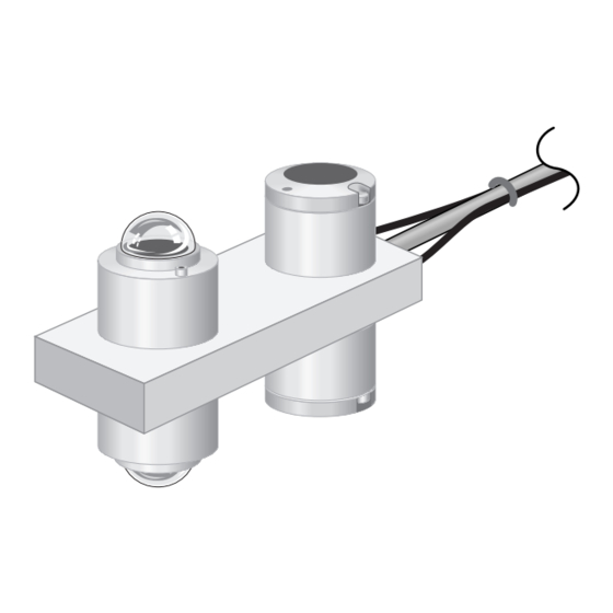
CNR1 Net Radiometer Cable length: 15 m (each cable) Weight: 4 kg Mounting arm attached to CNR1: 14.5” (37 cm) long 5/8” (1.6 cm) diameter FIGURE 2-1. The Dimensions of the CNR1 2.2 CM3 Specifications Specifications that are part of the ISO classification: Response time 95%: 18 s Non-stability:... -
Page 7: Cg3 Specifications
CNR1 Net Radiometer Tilt response: Max. dev. 2% Overall ISO classification: second class Sensitivity: 10 - 35 µV/(W m Impedance: 125 Ohm nominal -40°C to +80°C Operating temperature: 305-2800 nm (50% points) Spectral range: Expected signal range for atmospheric application: 0 - 15 mV typical ±... - Page 8 CNR1 Net Radiometer Northern Hemisphere this implies that the Net Radiometer should be mounted south of the mast. It is suggested that the CNR1 is mounted at a height of at least 1.5 meters above the surface to avoid shading effects of the instruments on the soil and to promote spatial averaging of the measurement.
-
Page 9: Connecting And Using The Heater
The sensor power can be controlled using one of the 12V power switches built into Campbell dataloggers or using an external solid state switch such as a PSW12/SW12. The heater’s current drain is approximately 500 mA when using a 12V battery. -
Page 10: Measuring Far Infrared Radiation With The Cg3
CNR1 Net Radiometer 4.2 Measuring Far Infrared Radiation with the CG3 The downward-facing CG3 measures the Far Infrared radiation that is emitted by the ground. The upward-facing CG3 measures the Far Infrared radiation from the sky. As the sky is typically colder than the instrument, one can expect negative voltage signals from the upward-facing CG3. -
Page 11: Calculation Of The Albedo For Solar Radiation
CNR1 Net Radiometer 4.4 Calculation of the Albedo for Solar Radiation The albedo is the ratio of incoming and reflected Solar radiation. It is a figure somewhere between 0 and 1. Typical values are 0.9 for snow, and 0.3 for grassland. -
Page 12: Calculation Of The Net (Total) Radiation
5-2 are applicable only if you bought the CNR1 Net Radiometer from Campbell Scientific, Inc. Use of the CNR1 Net Radiometer, which you bought outside of Campbell Scientific, is possible only on the CR3000 and CR5000 dataloggers. The PT-100 can connect directly to the CR3000 and CR5000 because they have current excitation inputs. -
Page 13: Cnr1 Schematic
CNR1 Net Radiometer FIGURE 5-1. CNR1 Schematic DATALOGGER 4WPB100 CNR1 Yellow PT-100 Green Blue FIGURE 5-2. Interfacing the Pt-100 Using the 4WPB100 Module... -
Page 14: Datalogger Connections For Differential Measurement, When Using A 4Wpb100
CNR1 Net Radiometer The four radiation outputs can be measured using Differential or Single-Ended inputs on the datalogger. A differential voltage measurement (Instruction 2) is recommended because it has better noise rejection than a single-ended measurement. When differential inputs are used, jumper the low side of the input to AG or to keep the signal in common mode range. -
Page 15: Datalogger Programming
CNR1 Net Radiometer TABLE 5-3. CR3000 and CR5000 Connections for Differential Measurement Function Color CR3000/CR5000 CM3 Up Signal Differential Input (H) CM3 Up Reference Blue Differential Input (L) CM3 Down Signal White Differential Input (H) CM3 Down Reference Black Differential Input (L) CG3 Up Signal Grey or Orange Differential Input (H) -
Page 16: Calibration Factor
CNR1 Net Radiometer FIGURE 6-1. 4WPB100 Module 6.1 Calibration Factor Each CNR1 is provided with a ‘Certificate of Calibration’ by the manufacturer that shows the sensor serial number and ‘sensitivity’, or calibration factor. The serial number and sensitivity are also shown on a label attached to the sensor. The calibration factor is in units of μV/(W m ), which needs to be converted to units of (W m... - Page 17 CNR1 Net Radiometer 'CR1000 'Declare Variables and Units Public Batt_Volt Public CM3Up Public CM3Dn Public CG3Up Public CG3Dn Public CNR1TC Public CNR1TK Public NetRs Public NetRl Public Albedo Public UpTot Public DnTot Public NetTot Public CG3UpCo Public CG3DnCo Units Batt_Volt=Volts Units CM3Up=W/meter²...
-
Page 18: Example 2, Cr5000 Using Differential Channels (No 4Wpb100)14
CNR1 Net Radiometer 'Main Program BeginProg Scan(2,Sec,1,0) 'Default Datalogger Battery Voltage measurement Batt_Volt: Battery(Batt_Volt) 'CNR1 Net Radiometer measurements CM3Up, CM3Dn, CG3Up, CG3Dn, CNR1TC, CNR1TK, 'NetRs, NetRl, Albedo, UpTot, DnTot, NetTot, CG3UpCo, and CG3DnCo: VoltDiff(CM3Up,1,mV25,1,True,0,_60Hz,100.0,0) VoltDiff(CM3Dn,1,mV25,2,True,0,_60Hz,100.0,0) VoltDiff(CG3Up,1,mV7_5,3,True,0,_60Hz,100.0,0) VoltDiff(CG3Dn,1,mV7_5,4,True,0,_60Hz,100.0,0) ** BrHalf4W (CNR1TC,1,mV25,mV25,5,Vx1,1,2100,True ,True ,0,250,1.0,0) PRT(CNR1TC,1,CNR1TC,1,0) CNR1TK=CNR1TC+273.15 NetRs=CM3Up-CM3Dn... - Page 19 CNR1 Net Radiometer 'CR5000 Series Datalogger 'ANALOG INPUT CM3 UP - downwelling shortwave radiation signal (red) CM3 UP - downwelling shortwave radiation signal reference (blue) 'gnd CNR1 shield (clear) CM3 DOWN - upwelling shortwave radiation signal (white) CM3 DOWN - upwelling shortwave radiation signal reference (black) CG3 UP - downwelling longwave radiation signal (gray) CG3 UP - downwelling longwave radiation signal reference (yellow) CG3 DOWN - upwelling longwave radiation signal (brown)
- Page 20 CNR1 Net Radiometer 'Define Data Tables DataTable(Table1,True,-1) DataInterval(0,60,Min,10) Average(1,CM3Up,FP2,False) Average(1,CM3Dn,FP2,False) Average(1,CG3Up,FP2,False) Average(1,CG3Dn,FP2,False) Average(1,CNR1TC,FP2,False) Average(1,CNR1TK,FP2,False) Average(1,NetRs,FP2,False) Average(1,NetRl,FP2,False) Average(1,Albedo,FP2,False) Average(1,UpTot,FP2,False) Average(1,DnTot,FP2,False) Average(1,NetTot,FP2,False) Average(1,CG3UpCo,FP2,False) Average(1,CG3DnCo,FP2,False) EndTable 'Main Program BeginProg Scan(1,Sec,1,0) 'Default Datalogger Battery Voltage measurement Batt_Volt: Battery(Batt_Volt) 'CNR1 Net Radiometer measurements CM3Up, CM3Dn, CG3Up, CG3Dn, CNR1TC, CNR1TK, 'NetRs, NetRl, Albedo, UpTot, DnTot, NetTot, CG3UpCo, and CG3DnCo: 'CNR1 Sensitivity 7.30 uV/m^2 VoltDiff(CM3Up,1,mV20C,1,True,200,250,136.99,0)
-
Page 21: Example 3, Cr23X Program Using Differential Channels
CNR1 Net Radiometer 6.2.3 Example 3, CR23X Program Using Differential Channels Program Example 3 requires six differential channels and the 4WPB100 module to measure the four radiation outputs and the Pt-100 temperature sensor. The program measures the sensors every 2 seconds and calculates and stores the following data to final storage every 60 minutes: Array ID Year... - Page 22 CNR1 Net Radiometer ;{CR23X} ;Program Example 1 for CR23X datalogger ;CNR1 sensitivity for program example = 7.30 uV/W/m^2 ;Multiplier for measurement instructions = 1000/7.30 = 136.99 ;*Table 1 Program 01: 2 Execution Interval (seconds) ;Measure CM3 Up and CM3 Down (shortwave radiation) ;Note: Multiplier (Parameter 5) will be different for each CNR1 1: Volt (Diff) (P2) 1: 2...
- Page 23 CNR1 Net Radiometer ;Net CM3 shortwave radiation = CM3 Up - CM3 Down 6: Z=X-Y (P35) 1: 1 X Loc [ CM3_up ] 2: 2 Y Loc [ CM3_dn ] 3: 7 Z Loc [ Net_Rs ] ;Net CG3 longwave radiation = CG3 Up - CG3 Down 7: Z=X-Y (P35) 1: 3 X Loc [ CG3_up ]...
-
Page 24: Example 4, Cr23X Program Using Single-Ended Channels
CNR1 Net Radiometer 15: Z=X*Y (P36) 1: 25 X Loc [ scratch_1 ] 2: 27 Y Loc [ scratch_3 ] 3: 28 Z Loc [ scratch_4 ] 16: Z=X+Y (P33) 1: 3 X Loc [ CG3_up ] 2: 28 Y Loc [ scratch_4 ] 3: 11 Z Loc [ CG3_upCor ] 17: Z=X+Y (P33) - Page 25 CNR1 Net Radiometer Wiring for Program Example 4 Color Function Example CR23X Program Channels Used CM3 Up Signal Blue CM3 Up Reference White CM3 Down Signal Black CM3 Down Reference Grey or Orange CG3 Up Signal Yellow CG3 Up Reference Brown CG3 Down Signal Green...
-
Page 26: Calibration
CNR1 Net Radiometer ;Measure CNR1 temperature 3: Full Bridge w/mv Excit (P9) 1: 1 Reps 2: 22 50 mV, 60 Hz Reject, Slow, Ex Range 3: 22 50 mV, 60 Hz Reject, Slow, Br Range 4: 5 DIFF Channel 5: 1 Excite all reps w/Exchan 1 6: 4200 mV Excitation... -
Page 27: Troubleshooting
CNR1 Net Radiometer 8. Troubleshooting If there is no clue as to what may be the problem, start performing the following "upside-down test", which is a rough test for a first diagnosis. It can be performed both outdoors and indoors. Indoors, a lamp can be used as a source for both Solar and Far Infrared radiation. -
Page 28: Testing Of The Cg3
CNR1 Net Radiometer 8.2 Testing of the CG3 It is assumed that the amplifier circuit is the same as the one used for the CM3, and that its zero offset is no more than a few watts per square meter, let us say 5 Watts per square meter just as an example (see second test in 7.1). -
Page 29: Different Conditions
Appendix A. CNR1 Performance and Measurements under Different Conditions Below, Table A-1, shows an indication of what one might typically expect to measure under different meteorological conditions. The first parameter is day and night. At night, the Solar radiation is zero. The second column indicates if it is cloudy or clear. - Page 30 Appendix A. CNR1 Performance and Measurements under Different Conditions TABLE A-1. Typical output signals of CNR1 under different meteorological conditions. Explanation can be found in the text. Cloudy +20 ºC ground Pt 100 sky T night clear - 20 ºC cloud 0-500 0-150...
-
Page 31: General Information
Appendix B. Details about Using the Heater Whenever the heater is used, the heating may cause errors in the NOTE measurement of the sensor temperature, see chapter 1.1.2.3. in Kipp Zonen CNR1 manual (http://www.kippzonen.com/?download/85182/CNR+1+Net+Ra diometer+-+Manual+(English).aspx), two degrees typical, and zero offsets in the CM3 (10 Watts per square meter typical). Under most conditions the accuracy that is gained by heating will be larger than the errors that are introduced by heating. - Page 32 Appendix B. Details about Using the Heater For decisions about heating one can make the following diagram: Not available 12 VDC, 6 VA available? DO NOT HEAT Available Consider options below Not Available DO NOT HEAT Clock and relay available? (CSI recommendation) Available Heat from 1 hour before the sunset...
-
Page 33: Cr3000/Cr5000 Program That Controls
0% at 33 degrees C above the dew point. If necessary, the user can change the two duty-cycle slope transitions. 'CR3000 or CR5000 Series Datalogger 'CR3000 Series Datalogger 'Copyright (c) 2009 Campbell Scientific, Inc. All rights reserved. '11 March 09 'version 0.0 '*** Wiring ***... - Page 34 Appendix C. CR3000/CR5000 Program that Controls the Heater '14H CNR1 upwelling longwave radiation signal (purple or pink) '14L CNR1 upwelling longwave radiation signal reference (gray) 'CURRENT EXCITATION 'IX1 CNR1 Pt100 current excitation (white) 'IXR CNR1 Pt100 current excitation reference (green) 'CONTROL PORTS SW12V control (green) SW12V control/power reference (black)
- Page 35 Appendix C. CR3000/CR5000 Program that Controls the Heater Alias nr01(3) = Rs_downwell Alias nr01(4) = Rs_upwell Alias nr01(5) = Rl_downwell Alias nr01(6) = Rl_upwell Alias nr01(7) = t_nr01 Alias nr01(8) = Rl_down_meas Alias nr01(9) = Rl_up_meas Units panel_temp = C Units batt_volt = V Units t_hmp = C Units rh_hmp = percent...
- Page 36 Appendix C. CR3000/CR5000 Program that Controls the Heater BeginProg Scan (1,Sec,0,0) 'Control the net radiometer heater. PWM (duty_cycle,4,250,mSec) 'Datalogger panel temperature. PanelTemp (panel_temp,250) 'Measure battery voltage. Battery (batt_volt) 'Measure the HMP45C temperature and relative humidity. VoltDiff (t_hmp,1,mV1000C,5,TRUE,200,250,0.1,-40) VoltDiff (rh_hmp,1,mV1000C,6,TRUE,200,250,0.1,0) 'Measure NR 01 Net Radiometer. Resistance (t_nr01,1,mV200,10,Ix1,1,1675,TRUE,TRUE,200,250,1,0) VoltDiff (Rs_downwell,1,mV20C,11,TRUE,200,250,NR01_SHORT_DW_CAL,0) VoltDiff (Rs_upwell,1,mV20C,12,TRUE,200,250,NR01_SHORT_UW_CAL,0)
- Page 37 Appendix C. CR3000/CR5000 Program that Controls the Heater Case Else duty_cycle = 0.01 EndSelect Else duty_cycle = 0.01 EndIf EndIf CallTable (stats) NextScan EndProg...
- Page 38 Appendix C. CR3000/CR5000 Program that Controls the Heater...
- Page 40 Campbell Scientific Companies Campbell Scientific, Inc. (CSI) 815 West 1800 North Logan, Utah 84321 UNITED STATES www.campbellsci.com • info@campbellsci.com Campbell Scientific Africa Pty. Ltd. (CSAf) PO Box 2450 Somerset West 7129 SOUTH AFRICA www.csafrica.co.za • cleroux@csafrica.co.za Campbell Scientific Australia Pty. Ltd. (CSA)
Need help?
Do you have a question about the CNR1 and is the answer not in the manual?
Questions and answers