Campbell CNR4 Product Manual
Net radiometer
Hide thumbs
Also See for CNR4:
- Instruction manual (70 pages) ,
- User manual (60 pages) ,
- Product manual (51 pages)

Subscribe to Our Youtube Channel
Related Manuals for Campbell CNR4


Summary of Contents for Campbell CNR4
- Page 1 CNR4 Net Radiometer Revision: 10/19 Copyright © 2000 – 2019 Campbell Scientific CSL I.D: 874...
- Page 3 Quotations for repairs can be given on request. It is the policy of Campbell Scientific to protect the health of its employees and provide a safe working environment, in support of this policy a “Declaration of Hazardous Material and Decontamination”...
- Page 5 PLEASE READ FIRST About this manual Please note that this manual was originally produced by Campbell Scientific Inc. primarily for the North American market. Some spellings, weights and measures may reflect this origin. Some useful conversion factors: Area: 1 in...
- Page 7 • Periodically (at least yearly) check electrical ground connections. WHILE EVERY ATTEMPT IS MADE TO EMBODY THE HIGHEST DEGREE OF SAFETY IN ALL CAMPBELL SCIENTIFIC PRODUCTS, THE CUSTOMER ASSUMES ALL RISK FROM ANY INJURY RESULTING FROM IMPROPER INSTALLATION, USE, OR MAINTENANCE OF TRIPODS, TOWERS, OR ATTACHMENTS TO TRIPODS AND TOWERS...
-
Page 9: Table Of Contents
2. Precautions ..............1 3. Initial Inspection ............1 Ships With ....................1 4. QuickStart ..............1 5. Overview ..............4 6. Specifications ............5 CNR4 Specifications ................6 Pyranometer Specifications ..............7 Pyrgeometer Specifications ..............8 Optional CNF4 Heater/Ventilator ............8 6.4.1 CNF4 Specifications ..............9 7. - Page 10 7-3. The CNR4 sensor with SOLAR and TEMP cables ......12 7-4. The marks on the end of the CNR4: S for SOLAR cable, and T for TEMP cable................12 7-5. Labels on the pigtail end of the SOLAR cable ........13 7-6.
- Page 11 7-2. TEMP Cable (Wire Colour, Function, and Data Logger Connection) ..................14 8-1. Resistance values versus CNR4 thermistor temperature in °C ... 18 8–2. Resistance values versus CNR4 Pt–100 temperature in °C ....19 B-1. Typical output signals of CNR4 under different meteorological conditions.
-
Page 13: Introduction
CNR4 Net Radiometer Introduction The CNR4 is a research-grade net radiometer that measures the energy balance between incoming and outgoing radiation. Our data loggers measure the CNR4 output. This net radiometer offers a professional solution for scientific-grade energy balance studies. - Page 14 Open Short Cut and create a new program. Double-click the data logger model. In the Available Sensors and Devices box, type CNR4 or locate the sensor in the Sensors > Meteorological > Solar Radiation folder. Double-click CNR4 Net Radiation. Type the sensitivity values supplied on the manufacturer certificate of calibration;...
- Page 15 CNR4 Net Radiometer Click on the Wiring tab to see how the sensor is to be wired to the data logger. Click OK after wiring the sensor. Repeat steps three and four for other sensors. Click Next. In Output Setup, enter the scan rate, Data Output Storage Intervals,...
-
Page 16: Overview
The pyranometer pair measures short-wave solar radiation, and the pyrgeometer pair measures long-wave far infrared radiation. The upper long- wave detector of CNR4 has a meniscus dome to ensure that water droplets roll off easily while improving the field of view to nearly 180°, compared with a 150°... -
Page 17: Specifications
The integrated heater can be used to melt frost. The CNR4 design is such that both the upward facing and the downward- facing instruments measure the energy that is received from the whole hemisphere (180°... -
Page 18: Cnr4 Specifications
CNR4 Net Radiometer FIGURE 6-1. The CNR4 net radiometer with cables and mounting rod, top view FIGURE 6-2. The CNR4 net radiometer with CNF 4 heater/ventilator unit, top view CNR4 Specifications Sensor sensitivities: Four probes with unique sensitivity values. Please refer to the calibration sheets or label on the bottom of the sensor for the sensitivity values. -
Page 19: Pyranometer Specifications
CNR4 Net Radiometer Cable length: User defined Weight Sensor: 0.85 kg (1.89 lb) without cables Heater/ventilator, CNF4 (optional): 0.50 kg (1.11 lb) without cables Mounting rod: 34.7 cm (13.67 in) length 1.6 cm (0.63 in) diameter Pyranometer Specifications Spectral range:... -
Page 20: Pyrgeometer Specifications
CNR4 Net Radiometer Uncertainty in daily total: < 5% (95% confidence level) Instrument calibration: Indoors. Side by side against reference CMP3 pyranometer according to ISO 9847:1992 annex A.3.1 Indicates ISO specifications. Pyrgeometer Specifications Spectral range: 4.5 to 42 μm (50% points) Sensitivity: 5 to 15 μV/W/m... -
Page 21: Cnf4 Specifications
For example, in the Northern Hemisphere, point the cable toward the North Pole. Mounting A mounting bracket kit is used to mount the CNR4 directly to a vertical pipe, or to a crossarm. Mount the sensor as follows: Attach the mounting rod to the CNR4 (see FIGURE 7-1). -
Page 22: Attaching The Mounting Rod To The Cnr4 Body
This includes both the incoming and outgoing sections of the sensor. FIGURE 7-2. Attaching the CNR4 onto the mounting rod using vertical pole or horizontal crossarm... -
Page 23: Wiring
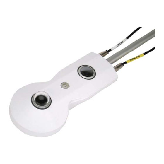
CNF4 heater/ventilator unit has power wires for heater and ventilator and a control/pulse wire for the tachometer. The CNR4 has a SOLAR cable and a TEMP cable (FIGURE 7-3). Connect the SOLAR cable to the S port and the TEMP cable to the T port (FIGURE 7-4). -
Page 24: The Cnr4 Sensor With Solar And Temp Cables
CNR4 Net Radiometer FIGURE 7-3. The CNR4 sensor with SOLAR and TEMP cables FIGURE 7-4. The marks on the end of the CNR4: S for SOLAR cable, and T for TEMP cable The four radiation outputs can be measured using differential or single-ended inputs on the data logger. -
Page 25: Labels On The Pigtail End Of The Solar Cable
CNR4 Net Radiometer FIGURE 7-5. Labels on the pigtail end of the SOLAR cable TABLE 7-1. SOLAR Cable (Wire Colour, Function, and Data Logger Connection) Wire Differential Data Logger Connection Single-Ended Data Logger Colour Wire Function Terminal Connection Terminal U configured for differential high... -
Page 26: Data Logger Programming
CNR4 Net Radiometer TABLE 7-2. TEMP Cable (Wire Colour, Function, and Data Logger Connection) Data Logger Connection Terminal Wire Colour Wire Function Using Thermistor Using Pt-100 U configured for single-ended analogue input White Thermistor Signal SE (single-ended, analogue-voltage input) Thermistor Voltage... -
Page 27: Sensor Sensitivity
CNF4 in a visible location. The extra label containing the serial number and sensitivity values is supplied with the purchase of the CNR4. Please refer to Appendix C, CNF4 Heater/Ventilator , for more details. -
Page 28: Operation
CNR4 Net Radiometer Where, Rf = thermistor resistance in ohms (for example, for a 10 kohm thermistor, Rf is 10000) Vx = value returned by the BrHalf() instruction The Steinhart-Hart equation is used to convert resistance to temperature. The Steinhart-Hart equation for converting resistance to degree Celsius is as follows: Temperature = 1(1.0295e-3+2.391e-4 x LN(Rs)+1.568e-7 x (LN(Rs))^3)-... -
Page 29: Long-Wave Far Infrared Radiation Measurements
T, into account. This is why the temperature sensors are incorporated in the CNR4 body near the pyrgeometer sensing element, and has, therefore, the same temperature as the pyrgeometer sensor surface. The calculation of the long-wave far infrared irradiance, E, is done according to Equation 8-2. - Page 30 8523 2854 Relatively small errors occur when the CNR4 is not in thermal equilibrium. This happens for example when the heater is on, or when the sun is shining. When the heater and ventilator are on, the largest expected deviation between the real sensor temperature and the thermistor reading is 1 degree.
-
Page 31: Calculation Of Albedo
Pt-100 requires one current excitation terminal, and one differential analogue terminal. The CR6, CR3000, and CR5000 have current excitation terminals. TABLE 8–2 shows the Pt-100 resistance values as a function of temperature. TABLE 8–2. Resistance values versus CNR4 Pt–100 temperature in °C Temperature Resistance Temperature Resistance... -
Page 32: Calculation Of Net Short-Wave Radiation
Equation 8-5, the terms that contain the sensor body temperature, T, cancel each other. Therefore, if only interested in the net long-wave radiation, instead of separate upper and lower components of the long-wave radiation, the CNR4 temperature measurement is not required. -
Page 33: Calculation Of Net (Total) Radiation
CNR4 Net Radiometer Calculation of Net (Total) Radiation In the four separate components mode, net radiation, R , can be calculated using the individual sensor measurement results: = [(E upper Pyranometer) - (E lower Pyranometer)] (8-8) + [(E upper Pyrgeometer) - (E lower Pyrgeometer)] Where E upper/lower pyranometers are calculated according to Equation 8-1, and E upper/lower pyrgeometers are calculated according to Equation 8-2. -
Page 34: Testing The Pyrgeometer
(see second test in Section 9.1.1, Testing the Pyranometer (p. 21) The CNR4 body and the ambient air should be at the same temperature. Let the pyrgeometer rest for at least five minutes to regain its thermal equilibrium. Set the voltmeter to its most sensitive range. To test if the pyrgeometer is working properly, put your hand in front of the pyrgeometer. -
Page 35: Maintenance
9.2.2 Replacing the Drying Cartridge The CNR4 has a drying cartridge inside the sensor to help keep the electronics dry. The manufacturer recommends replacing the drying cartridge every 6 to 12 months. - Page 36 CNR4 Net Radiometer two-day period and, then, comparing the results. For comparison of pyranometers, one should use a clear day. For comparison of pyrgeometers, one should compare the nighttime results. If the deviations are greater than 6%, the sensor should be recalibrated.
-
Page 37: Importing Short Cut Code Into Crbasic Editor
Appendix A. Importing Short Cut Code Into CRBasic Editor Short Cut creates a .DEF file that contains wiring information and a program file that can be imported into the CRBasic Editor. By default, these files reside in the C:\campbellsci\SCWin folder. Import Short Cut program file and wiring information into CRBasic Editor: Create the Short Cut program. - Page 39 This can roughly be attributed to the water vapour in the air, which is a major contributor to the far infrared radiation. TABLE B-1. Typical output signals of CNR4 under different meteorological conditions. Explanation can be found in the text.
-
Page 40: Cnr4 Performance And Measurements Under Different Conditions
Appendix B. CNR4 Performance and Measurements under Different Conditions FIGURE B-1. Different measurement conditions and signals Upper pyrgeometer Day with alternating cloud fields Upper Pyrgeometer Day with Alternating Cloud Fields pyrgeometer: U_emf / Sensitivity [W/m²] Temp YSI 44031 [°C] -100... - Page 41 Appendix B. CNR4 Performance and Measurements under Different Conditions Upwelling Signal (Downward Facing) Pyrgeometer upwelling signal (downward facing) pyrgeometer Pyrgeometer: U-emf / sensitivity [W/m²] Temp of instrument [°C] FIGURE B-3. Clear day for the downward facing pyrgeometer It is assumed that when ambient temperature varies, the net far infrared radiation remains roughly the same, independent of ambient temperature.
- Page 42 Appendix B. CNR4 Performance and Measurements under Different Conditions upper Temperatur (C-1) − ⋅ lower Ground Temperatur − ⋅ (C-2)
-
Page 43: Cnf4 Heater/Ventilator
Appendix C. CNF4 Heater/Ventilator NOTE Whenever the heater is used, the heating may cause errors in the measurement of the sensor temperature. Under most conditions, the accuracy gained by heating will be larger than the errors introduced by heating. In both the pyranometer and the pyrgeometer, thermal sensors are used, and these sensors, in principle, measure a heat flow. - Page 44 The heater power can be controlled using one of the SW12V terminals of the Campbell Scientific data loggers. The heater current drain is approximately 850 mA at 12 VDC (10 W). The ventilator draws additional 5 W of power at 12 VDC.
-
Page 45: Attaching The Optional Cnf4 Heater/Ventilator Unit To Cnr4
Appendix C. CNF4 Heater/Ventilator C.2 Attaching the Optional CNF4 Heater/Ventilator Unit to CNR4 The CNF4 heater/ventilator unit comes with the following: the heater/ventilator, the white solar shield, three pan-head screws with washers, and four flat-head screws as shown in FIGURE C-1. -
Page 46: Attaching The Cnf4 To Cnr4 Using Pan-Head Screws And Washers
Appendix C. CNF4 Heater/Ventilator Attach the heater/ventilator unit unto the bottom of the CNR4 sensor, using the three pan-head screws and washers, as shown in FIGURE C-2. Make sure that the pyranometer and the pyrgeometer windows are not scratched during the installation. - Page 47 Appendix C. CNF4 Heater/Ventilator Make sure the cables are cleared from the edges of the CNF4, as shown in FIGURE C-3, and place the white solar shield over it. Use the four flat- head screws provided to complete the solar shield installation to the CNF4, as shown in FIGURE and FIGURE C-5.
- Page 48 Once the CNF4 heater/ventilator unit is attached to the bottom side of the CNR4, the CNF4 will cover the label that contains the serial number and the sensitivity values for the four sensors. Affix the extra label that came with the sensor to the bottom side of the CNF4 anodized aluminium base so that the label is in a visible location.
-
Page 49: Wiring
Depending on the data logger that is used with the CNR4-L and the older, four-wire version of the CNF4-L, the tachometer output may not work for 25-m (82-ft) or 50-m (164-ft) cables. -
Page 50: Data Logger Programming For Heater/Ventilator Control
Appendix C. CNF4 Heater/Ventilator TABLE C-1. Data Logger Connections for Differential Measurement with Heater/Ventilator Control Function Wire Data Logger Terminal Colour Thermistor U configured for single-ended , SE (single-ended, Thermistor Signal White analogue input analogue-voltage input) Thermistor Voltage U configured for voltage excitation Excitation EX, VX (voltage excitation) Thermistor Signal... -
Page 51: Cnf4 Heater/Ventilator Maintenance
Appendix C. CNF4 Heater/Ventilator the CNR4 should be connected to the 12V terminal. An A21REL-12 can be used to switch 12V to reduce current consumption. An example program that measures the CNR4, controls the heater/ventilator using measurements provided by the EE181 temperature and relative humidity sensor, measures the tachometer, and uses the A21REL-12 to switch 12V power is provided at www.campbellsci.eu/downloads/cnr4-cnf4-example-program. - Page 52 INFO Global Sales & Support Network A worldwide network to help meet your needs Australia France Thailand Garbutt, QLD Australia Vincennes, France Bangkok, Thailand Location: Location: Location: Phone: 61.7.4401.7700 Phone: 0033.0.1.56.45.15.20 Phone: 66.2.719.3399 info@campbellsci.com.au info@campbellsci.fr info@campbellsci.asia Email: Email: Email: www.campbellsci.com.au www.campbellsci.fr www.campbellsci.asia Website:...
Need help?
Do you have a question about the CNR4 and is the answer not in the manual?
Questions and answers